
Riser tube placing device of double-station anti-gravity casting machine for large copper alloy propellers

A technology of anti-gravity casting and riser tubes, which is applied in the field of placement devices for riser tubes of double-station anti-gravity casting machines, to achieve the effects of filling molds, shortening distances, and simple structures

Active Publication Date: 2018-11-30
HARBIN INST OF TECH
View PDF10 Cites 4 Cited by
  • Summary
  • Abstract
  • Description
  • Claims
  • Application Information

AI Technical Summary

Problems solved by technology

[0004] The purpose of the present invention is to solve the problem that the liquid riser of the existing anti-gravity casting machine interferes with the movement of the lower tank, and provide a large-scale copper alloy propeller double-station anti-gravity casting machine liquid riser placement device

Method used


Image

  • Riser tube placing device of double-station anti-gravity casting machine for large copper alloy propellers
  • Riser tube placing device of double-station anti-gravity casting machine for large copper alloy propellers
  • Riser tube placing device of double-station anti-gravity casting machine for large copper alloy propellers

Examples


specific Embodiment approach 1

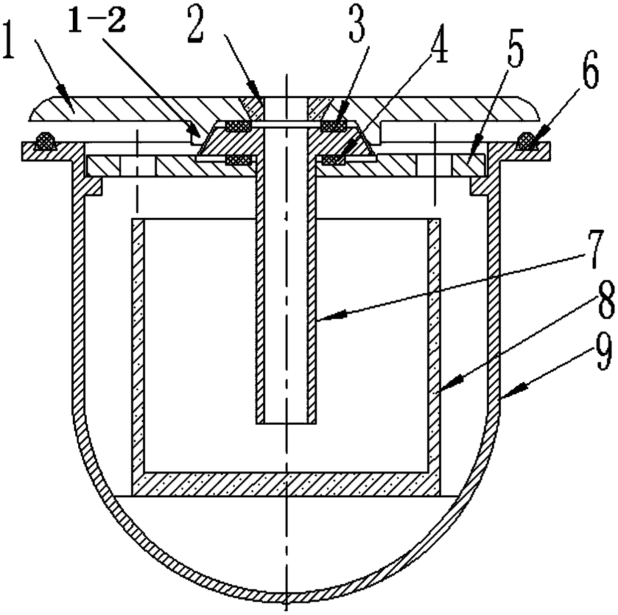
[0017] Specific Embodiment 1: In this embodiment, the large-scale copper alloy propeller double-station anti-gravity casting machine riser installation device includes a middle partition 1, an upper seal ring 3, a lower seal ring 4, a support plate 5, a riser pipe 7 and copper The water bag 8 and the copper water bag 8 are arranged in the lower tank 9, and a positioning convex edge platform 9-1 is arranged on the tank inner wall of the lower tank 9, and the support plate 5 is in the shape of a disc, and a liquid liter is opened at the center of the support plate 5. Pipe insertion hole 5-1, the upper plate surface of support plate 5 has circular positioning groove 5-2, also has sealing ring positioning groove 5-3 in the groove of circular positioning groove 5-2, circular positioning The groove 5-2, the sealing ring positioning groove 5-3 and the riser pipe insertion hole 5-1 form a concentric circle structure, and a plurality of ventilation holes 5-4 are opened in the circumfere...

specific Embodiment approach 2

[0019] Embodiment 2: The difference between this embodiment and Embodiment 1 is that the support plate 5 is uniformly opened with four ventilation holes 5-4 in the circumferential direction.

specific Embodiment approach 3

[0020] Embodiment 3: The difference between this embodiment and Embodiment 1 or 2 is that the lower tank flange 9-2 is arranged on the open edge of the lower tank 9 .


PUM


Abstract

The invention discloses a riser tube placing device of a double-station anti-gravity casting machine for large copper alloy propellers and relates to a riser tube placing device of a double-station anti-gravity casting machine. The invention solves the problem that a riser tube of the anti-gravity casting machine interferes with movement of a lower tank. The riser tube placing device comprises a middle partition plate, an upper seal ring, a lower seal ring, a supporting plate, the riser tube and a molten copper ladle. The molten copper ladle is arranged in the lower tank, a riser tube insertion hole is formed in the center of circle of the supporting plate, the supporting plate is arranged on a positioning protruding edge of the lower tank, the riser tube flange is arranged at one tube endof the tube body of the riser tube, the riser tube is vertically inserted into the riser tube insertion hole of the supporting plate and stretches into the molten copper ladle, a flange seat matchedwith the riser tube flange is arranged on a lower panel of the middle partition plate, and an orthogonal mouth sleeve is arranged in the thickness direction of the middle partition plate. The riser tube is integrally arranged below the middle partition plate, so that the lower tank drives the riser tube to move on a bed body guide rail to adjust different stations.

Description

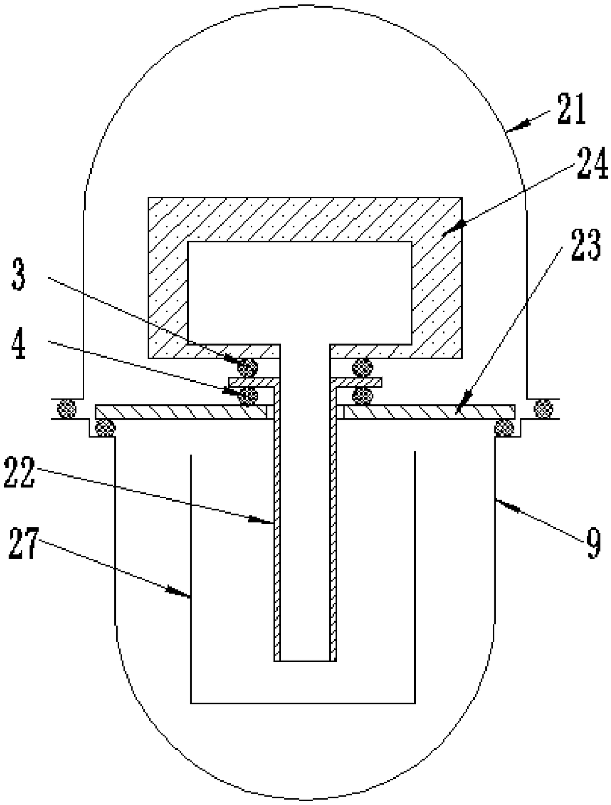
technical field [0001] The invention relates to a placement device for a riser pipe of a double-station anti-gravity casting machine. Background technique [0002] In the existing single-station anti-gravity casting machine (small low pressure or differential pressure), the lower tank does not need to be moved, and the structure is relatively simple. The existing traditional placement device structure such as figure 1 As shown, the traditional riser 22 is inserted into the crucible 27 in the lower tank 9 from the through hole provided on the working platform 23, and then the casting mold 24 is placed on the working platform 23, and the casting mold 24 is arranged in the upper tank 21 . The upper sealing ring 3 and the lower sealing ring 4 of the riser are pressed by the weight of the mold and the locking force of the mold and the middle partition, thereby realizing the sealing of the riser and the mold and the riser and the lower tank. This structure for placing the liqui...

Claims


Application Information

Patent Timeline
IPC IPC(8): B22D18/04
CPCB22D18/04
Inventor 曹福洋孙剑飞宁志良黄永江彭德林宋和谦
Owner HARBIN INST OF TECH
Learn More