
Capacitor voltage transformer unit impulse response solution method based on square-wave pulse

A unit impulse response, voltage transformer technology, applied in instruments, measuring electrical variables, measuring devices, etc., can solve the problems of inaccurate data, waste of material resources, time and manpower, inaccurate calculation of transfer characteristics, etc., and achieve fast and accurate algorithms. , cost saving effect

Inactive Publication Date: 2018-11-27
SICHUAN UNIV
View PDF5 Cites 1 Cited by
  • Summary
  • Abstract
  • Description
  • Claims
  • Application Information

AI Technical Summary

Problems solved by technology

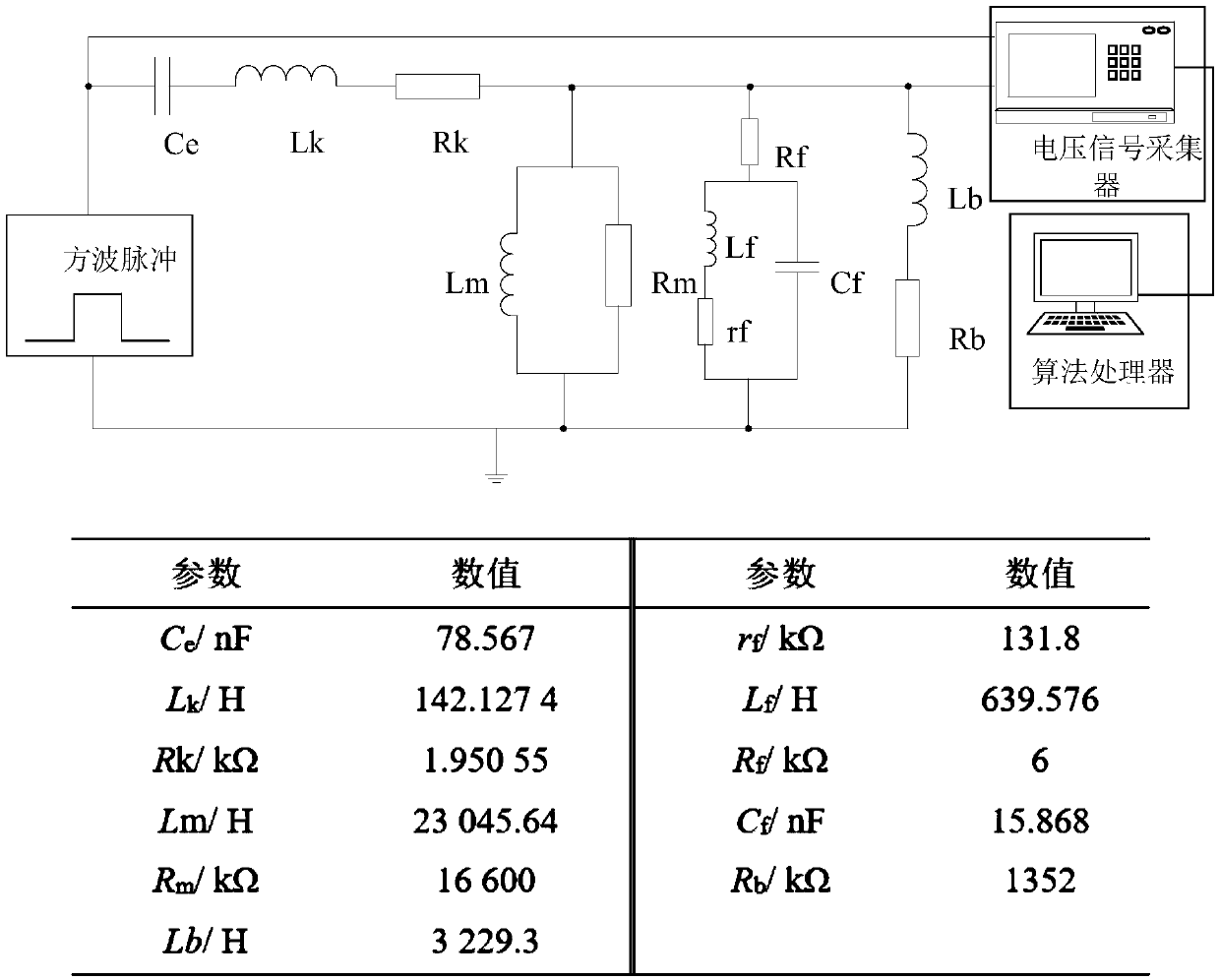
[0004] The invention solves the problem of inaccurate calculation of transfer characteristics due to manufacturing factors and unknown parameter stray capacitances in the transfer characteristic measurement of capacitive voltage transformers in the prior art, and provides a capacitive voltage transformer based on square wave pulses The unit impulse response solution method, which is applied based on the zero-state response process of the system, injects high-voltage pulses at the high-voltage end of the equipment, collects voltage signals at the high-voltage injection end and low-voltage output end, and calculates the system unit impulse by using the finite-length convolution formula. Response, that is, the time-domain transfer characteristics of the capacitive voltage transformer, ensures the accuracy of the transfer characteristic calculation, and avoids the huge waste of material resources, time and manpower in the harmonic power supply test, and instead obtains inaccurate data

Method used


Image

  • Capacitor voltage transformer unit impulse response solution method based on square-wave pulse
  • Capacitor voltage transformer unit impulse response solution method based on square-wave pulse
  • Capacitor voltage transformer unit impulse response solution method based on square-wave pulse

Examples


Embodiment

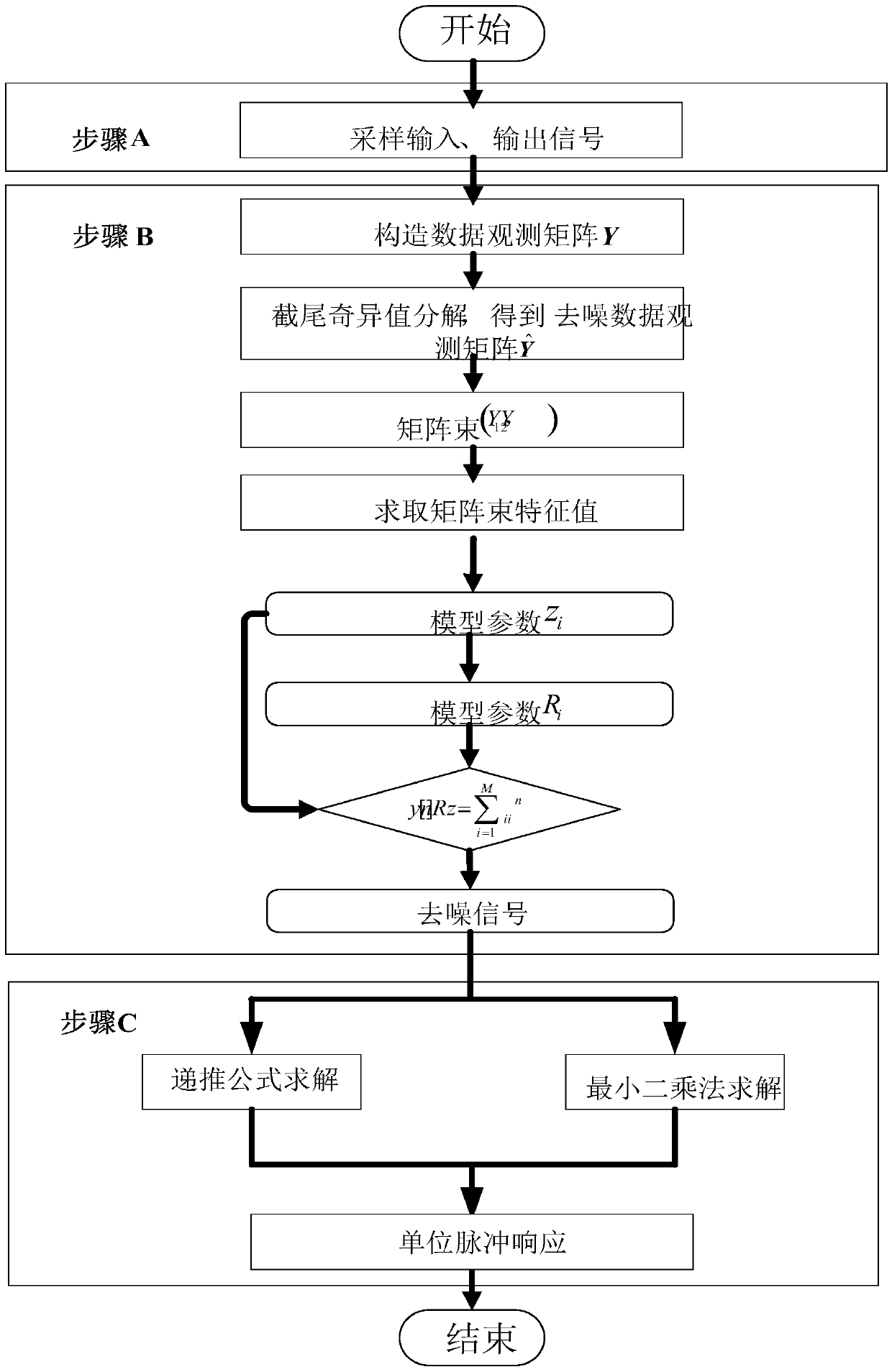
[0040] Such as figure 1 As shown, the method for solving the unit impulse response of a capacitor voltage transformer based on square wave pulses includes the following steps: A. In the offline state, inject a high-voltage pulse into the high-voltage input terminal of the capacitor voltage transformer, and inject a high-voltage pulse at the high-voltage input terminal and low-voltage output terminal The terminal is connected to the data collector to collect signals with the same sampling frequency;

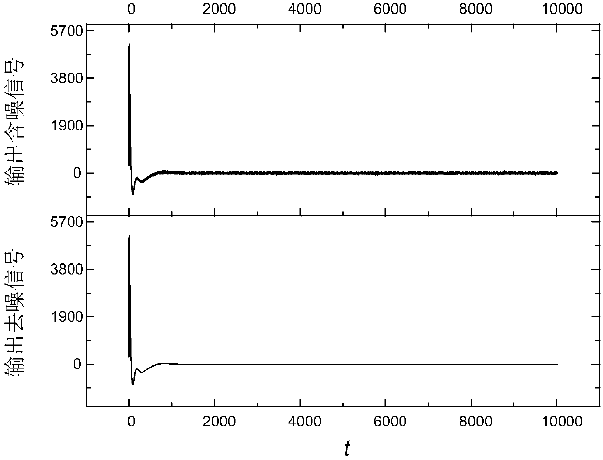
[0041] B. Carry out matrix beam denoising fitting to the signals at each end obtained in step A, to reduce the adverse interference of noise on the inversion operation;

[0042] The matrix beam denoising fitting process includes the following steps:

[0043] B1. Assuming that the sampling signal at the bus end is y[n], construct the data observation matrix,

[0044]

[0045] In the formula, N sampling length, L=N / 3~N / 4;

[0046] B2. Singular value decomposition is performed ...


PUM


Abstract

The invention discloses a capacitor voltage transformer unit impulse response solution method based on square-wave pulse. The method comprises the following steps: under an offline state, high-voltagepulse is injected into the high voltage input end of a capacitor voltage transformer, and data collectors are connected to the high voltage input end and the low voltage output end to be used for collecting signals according to the same sampling frequency; matrix pencil denoising fitting is performed on obtained signals of all the ends; a recursion formula and a linear equation system are designed according to a finite length convolution formula, and convolution inversion operation is performed on denoised signals to obtain unit impulse response of the capacitor voltage transformer. The method disclosed by the invention solves the problem of inaccurate transmission characteristic calculation caused by internal unknown-parameter stray capacitance in the prior art. When the capacitor voltage transformer unit impulse response solution method based on square-wave pulse is utilized, the high-voltage pulse is injected into the high-voltage end of equipment, the voltage signals are collectedat the high-voltage injection end and the low-voltage output end, and the finite length convolution formula is utilized to perform deconvolution and calculate out system unit impulse response.

Description

technical field [0001] The invention relates to a method for researching transfer characteristics of a capacitive voltage transformer, in particular to a method for solving a unit impulse response of a capacitive voltage transformer based on a square wave pulse. Background technique [0002] Capacitive voltage transformer is a kind of voltage measurement equipment, which has been widely used in my country's 35kV and above power grids, and its measurement data is used for relay protection devices and power quality measurement devices. Its transfer characteristics have the characteristics of large harmonic measurement error and poor transient characteristics, which have adverse effects on the accurate action of the relay protection system, power quality monitoring and measurement, and fault feature analysis and prevention. Analyzing the transfer characteristics of capacitive voltage transformers is of great significance for transient signal compensation and harmonic recovery m...

Claims


Application Information

Patent Timeline
IPC IPC(8): G01R35/02
CPCG01R35/02
Inventor 徐方维舒勤李佳涵
Owner SICHUAN UNIV
Learn More