
Electro-hydraulic mix-drive vertical lifting device

A hybrid drive, hydroelectric technology, applied in fluid pressure actuation devices, lifting devices, fluid pressure actuation system components, etc., can solve the problems of shock, vibration, high installation accuracy, and low system power-to-weight ratio. Achieve the effect of low cost, convenient operation and high control precision

Active Publication Date: 2018-11-27
TAIYUAN UNIV OF TECH
View PDF8 Cites 2 Cited by
  • Summary
  • Abstract
  • Description
  • Claims
  • Application Information

AI Technical Summary

Problems solved by technology

However, when the chain drive is working, it has a lot of noise, shock and vibration, and requires high installation accuracy; at the same time, the use of hydraulic cylinders to drive the chain leads to low power-to-weight ratio and low efficiency of the system

Method used


Image

  • Electro-hydraulic mix-drive vertical lifting device
  • Electro-hydraulic mix-drive vertical lifting device
  • Electro-hydraulic mix-drive vertical lifting device

Examples


Embodiment 1

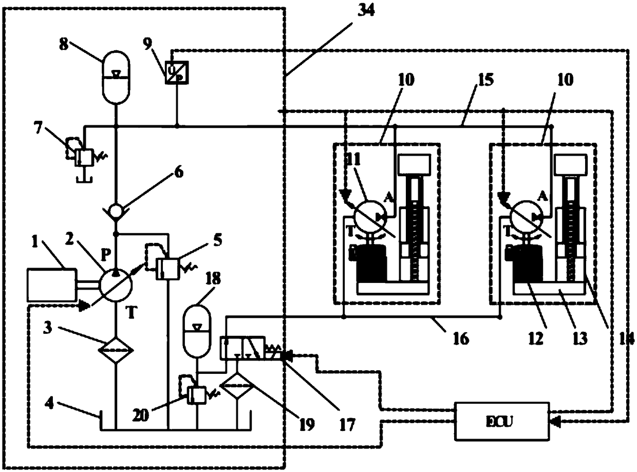
[0043] like Figure 2-3 As shown, a lifting device driven by a hydraulic-electric hybrid includes a power source, a main hydraulic pump, a filter I, a filter II, an oil tank, an overflow valve I, a check valve I, and an overflow valve II Valve, No. I hydraulic accumulator, pressure sensor, No. I driving cylinder, No. II driving cylinder, reversing valve, No. II hydraulic accumulator, No. III overflow valve, high-pressure pipeline and low-pressure pipeline;

[0044] The power source is mechanically connected with the main hydraulic pump, the oil suction port of the main hydraulic pump communicates with the oil tank through the first filter, and the oil outlet of the main hydraulic pump is connected with the oil inlet of the first one-way valve and the inlet of the first relief valve at the same time. The oil port is connected, the oil outlet of the first relief valve is connected with the oil tank, and the oil outlet of the first one-way valve is connected with the oil inlet of...

Embodiment 2

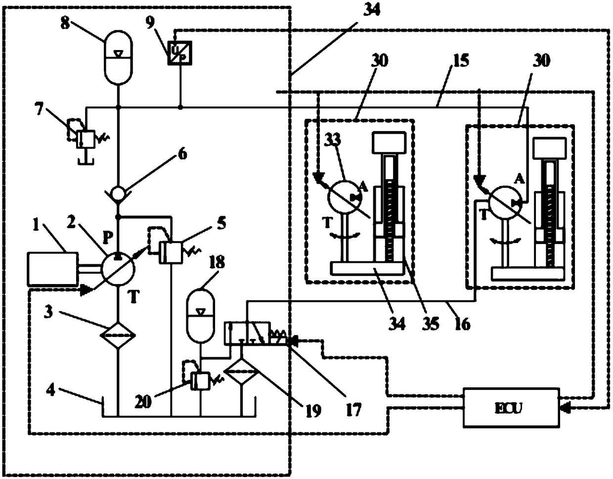
[0049] like Figure 4-5 As shown, a lifting device driven by a hydraulic-electric hybrid includes a power source, a main hydraulic pump, a filter I, a filter II, an oil tank, an overflow valve I, a check valve I, and an overflow valve II Valve, No. I hydraulic accumulator, pressure sensor, No. I driving cylinder, No. II driving cylinder, reversing valve, No. II hydraulic accumulator, No. III overflow valve, high-pressure pipeline and low-pressure pipeline;

[0050] The power source is mechanically connected with the main hydraulic pump, the oil suction port of the main hydraulic pump communicates with the oil tank through the first filter, and the oil outlet of the main hydraulic pump is connected with the oil inlet of the first one-way valve and the inlet of the first relief valve at the same time. The oil port is connected, the oil outlet of the first relief valve is connected with the oil tank, and the oil outlet of the first one-way valve is connected with the oil inlet of...


PUM


Abstract

The invention discloses an electro-hydraulic mix-drive vertical lifting device, which comprises a power source, a main hydraulic pump, a filter, an oil tank, a first overflow valve, a one-way valve, asecond overflow valve, a first hydraulic energy accumulator, a pressure sensor, a first driving cylinder, a second driving cylinder, a second hydraulic energy accumulator and a reversing valve. The working speed of an actuator is controlled by adjusting the displacement of a secondary element; when the vertical lifting device is lowered, the second hydraulic energy accumulator can achieve energyrecovery and reuse the energy when the system is started up next time; by using a variable pump / motor-motor-transmission case to drive a mechanical cylinder, the power-weight ratio of the system is greatly improved. According to the invention, the device has the advantages of simple structure, convenient operation, large power-weight ratio and capability of achieving energy recovery and reutilization.

Description

technical field [0001] The invention belongs to the technical field of vertical lifting devices, and in particular relates to a vertical lifting device driven by a hydraulic-electric hybrid drive. Background technique [0002] In order to adapt to the fierce competition in the market, meet the increasingly stringent demands of the market, and improve the quality and performance of lifting device products, various new technologies have been continuously applied to the design of modern lifting devices to promote the development of vertical lifting devices. develop. At present, the customer's demand for the vertical lifting device is mainly reflected in the demand for safety, reliability, maintainability, power-to-weight ratio and energy saving. Currently, the hydraulic system of the vertical lifting device of the transport vehicle on the market mainly adopts throttling and speed regulation, resulting in temperature rise and energy loss of the hydraulic system; because the var...

Claims


Application Information

Patent Timeline
Patent Type & Authority Applications(China)
IPC IPC(8): F15B1/02F15B11/16F15B21/14B66F9/22
CPCB66F9/22F15B1/02F15B11/16F15B21/14
Inventor 权龙葛磊陈正雄王波夏连鹏李泽鹏
Owner TAIYUAN UNIV OF TECH
Learn More