Spatial structure and printing method suitable for continuous fiber 3D printing

A continuous fiber, 3D printing technology, applied in the field of additive manufacturing of continuous fiber reinforced resin, composite material structure design and manufacturing, can solve the problem that lattice structures cannot be 3D printed by continuous fibers, and achieve accelerated lightweight application, quality The effect of light weight and short manufacturing cycle

Active Publication Date: 2020-07-10
AEROSPACE INST OF ADVANCED MATERIALS & PROCESSING TECH
View PDF7 Cites 0 Cited by
  • Summary
  • Abstract
  • Description
  • Claims
  • Application Information

AI Technical Summary

Problems solved by technology

[0005] The invention provides a spatial structure and printing method suitable for continuous fiber 3D printing, which can solve the technical problem that the dot matrix structure cannot be printed by continuous fiber 3D in the prior art

Method used


Image

  • Spatial structure and printing method suitable for continuous fiber 3D printing
  • Spatial structure and printing method suitable for continuous fiber 3D printing
  • Spatial structure and printing method suitable for continuous fiber 3D printing

Examples


example 1

[0034] Example 1: The spatial configuration of a quadrilateral

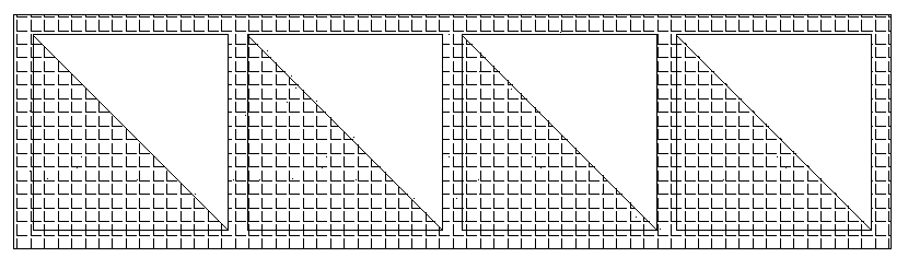
[0035] refer to figure 1 , 2 As shown in , 3, set the working surface of the printing platform as the X-Y plane. On this plane, the rod-shaped strut is a square column with a cross-sectional side length of 1mm, and the length of the rod-shaped strut is 10mm, forming a square frame of 10mm×10mm. body. Perpendicular to the X-Y plane, the rod is a cylinder with a side length of 1mm in section, the length of the rod is 10mm, the bearing area is a right triangle with a side length of 10mm, and a thickness of 1mm.

[0036] Materials used: the rod-like struts of the network structure are continuous carbon fiber-reinforced nylon, the rod-like struts are short carbon fiber-reinforced nylon, the core material of the load-bearing area is short carbon fiber-reinforced nylon with a thickness of 0.5mm, and the reinforced skin is continuous fiber with a thickness of 0.5mm Reinforced nylon.

[0037] The components of the ab...

example 2

[0038] Example 2, Triangular Space Configuration

[0039] refer to Figure 4 , 5 , 6, 7, the printing method of the triangle space structure is as follows:

[0040] 1. Use continuous fiber reinforced PLA to print the first layer of grid structure on the printer's working plane, such as Figure 5 , wherein the rod-shaped strut is a cylinder with a side length of 2 mm and a height of 10 mm, forming an equilateral triangle;

[0041] 2. On the plane perpendicular to the grid structure, use short carbon fiber reinforced nylon to print the rod-shaped rod and the core material of the triangular bearing area. At the connection point of each rod-shaped strut of the lattice structure. The thickness of the core material in the triangular bearing area is 1mm, one of the right-angled sides is a supporting rod, and the other right-angled side is a supporting rod, and it is printed outward along the inner side of the supporting rod.

[0042] 3. Use smaller nozzles and continuous fiber-r...


PUM

PropertyMeasurementUnit
thicknessaaaaaaaaaa

Abstract

The invention provides a spatial structure suitable for continuous fiber 3D printing. The spatial structure comprises a plurality of parallel lattice structures and bearing surfaces vertical to the adjacent lattice structures. Each lattice structure is composed of a rod-like supporting rod, and each bearing face is composed of a rod-like bar and a bearing region. Meanwhile, the invention providesa printing method suitable for continuous fiber 3D printing. By means of the spatial structure suitable for continuous fiber 3D printing, a lattice structure and 3D printing are combined, so that themanufactured material has the characteristics of being light in weight, high in bearing capacity and stable in mechanic bearing capacity on the structural unit, and is high in manufacturing speed, lowin technical difficulty and free of precision molds, and the manufacturing period is shortened.

Description

technical field [0001] The invention relates to the technical field of additive manufacturing using continuous fiber reinforced resin, and belongs to the technical field of composite material structure design and manufacturing. Background technique [0002] With the development of aerospace, more stringent requirements have been put forward for the lightweight and multifunctional material structure. Designers are looking for a high-load-bearing material that can replace ordinary sandwich materials such as honeycomb and foam, and provide a basis for aircraft weight reduction and flight increase. At present, the lattice structure presents unique advantages: different densities and loads can be designed according to requirements, and a large number of cavities are distributed inside, which can realize the integration of stealth, energy storage, damping and other functions, and is a structure-stealth integration. perfect combination. [0003] At present, the methods of lattice...

Claims


Application Information

Patent Timeline
Patent Type & Authority Patents(China)
IPC IPC(8): B29C64/165B33Y10/00B33Y80/00
CPCB29C64/165B33Y10/00B33Y80/00
Inventor 毕向军邓延方旭东浑丙利王红丽路建军缪伟民
Owner AEROSPACE INST OF ADVANCED MATERIALS & PROCESSING TECH
Why Eureka
Try Eureka