Laser welding fixing device for spectacle frame

A fixing device and laser welding technology, which is applied in the direction of laser welding equipment, auxiliary equipment, welding equipment, etc., can solve the problems of small size of nose pads and other components, low degree of automation, and difficulty in ensuring welding accuracy, so as to avoid inaccurate positioning Effect

Inactive Publication Date: 2018-11-23
江苏东方光学有限公司
View PDF0 Cites 0 Cited by
  • Summary
  • Abstract
  • Description
  • Claims
  • Application Information

AI Technical Summary

Problems solved by technology

[0002] The processing of existing spectacle frames needs to weld components such as nose pads, short nose bridge, long nose bridge and temples on the periphery of the frame. The traditional welding method is manual soldering (Soldering and Brazing), which has a low degree of automation. , and due to the small size of the nose pads and other components, the traditional brazing method is difficult to ensure the welding accuracy, resulting in a high scrap rate
[0003] With the popularization and promotion of laser welding technology, people are now using laser welding to weld spectacle frames, but the welding still requires manual positioning of the components of the spectacle frame before welding, and it is still difficult to ensure welding accuracy. Resulting in high scrap rate and low welding process efficiency

Method used


Image

  • Laser welding fixing device for spectacle frame
  • Laser welding fixing device for spectacle frame
  • Laser welding fixing device for spectacle frame

Examples


Embodiment Construction

[0019] The implementation of the present invention will be described in detail below with reference to the drawings and examples, so as to fully understand and implement the implementation process of how to use technical means to solve technical problems and achieve technical effects in the present invention.

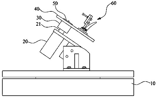
[0020] Please also refer to figure 1 , figure 1 It is a schematic diagram of a laser welding and fixing device for a mirror frame according to an embodiment of the present invention. As shown in the figure, a mirror frame laser welding and fixing device includes a base 10; a rotating motor 20 installed on the base 10, and the rotating motor 20 has a rotating main shaft 21; a positioning seat cover 30 fixed on the rotating main shaft 21; buckled on the positioning seat The clamp mounting plate 40 of the cover 30; the frame positioning mold 50 fixed to the clamp mounting plate 40 by bolts, and the bolts are set to the positioning seat cover 30; and the movable press butt...


PUM


Abstract

The invention discloses a laser welding fixing device for a spectacle frame. The device comprises a base, a rotary motor installed on the base, a positioning base sleeve, a clamp mounting plate, a spectacle frame positioning die and a movable buckle assembly, wherein the rotary motor is provided with a rotary main shaft, the positioning base sleeve is fixed to the rotary main shafts, and the clampmounting plate is buckled to the positioning base sleeve; the spectacle frame positioning die is fixed to the clamp mounting plate through bolts, and the bolts penetrate through the positioning basesleeve; the movable buckle assembly is installed on the clamp mounting plate. The to-be-welded spectacle frame is clamped through the spectacle frame positioning die, a corresponding nose bridge is placed in a nose bridge positioning groove and stabilized by the movable buckle assembly, the rotary motor is controlled to move by a numerical control system, then a corresponding laser welding head conducts spot welding back and forth, and the trouble of inaccurate positioning in the past is avoided.

Description

technical field [0001] The invention belongs to the technical field of spectacle frame processing, and in particular relates to a laser welding and fixing device for a spectacle frame. Background technique [0002] The processing of existing spectacle frames needs to weld components such as nose pads, short nose bridge, long nose bridge and temples on the periphery of the frame. The traditional welding method is manual soldering (Soldering and Brazing), which has a low degree of automation. , and due to the small size of the nose pads and other components, the traditional brazing method is difficult to ensure the welding accuracy, resulting in a high scrap rate. [0003] With the popularization and promotion of laser welding technology, people are now using laser welding to weld spectacle frames, but the welding still requires manual positioning of the components of the spectacle frame before welding, and it is still difficult to ensure welding accuracy. This results in a...

Claims


Application Information

Patent Timeline
Patent Type & Authority Applications(China)
IPC IPC(8): B23K37/047B23K26/70B23K26/22
CPCB23K37/047B23K26/22B23K26/702
Inventor 蔡国正
Owner 江苏东方光学有限公司
Why Eureka
Try Eureka