A permanent magnet fault-tolerant rim propulsion motor winding reconstruction method with reduced mutual inductance

A technology of rim propulsion and motor winding, which is applied to the shape/style/structure of the winding conductor to achieve the effects of reducing the thickness of the slot, reducing the mutual inductance, and reducing the leakage inductance of the slot

Active Publication Date: 2020-04-10
DALIAN MARITIME UNIVERSITY +1
View PDF8 Cites 0 Cited by
  • Summary
  • Abstract
  • Description
  • Claims
  • Application Information

AI Technical Summary

Problems solved by technology

Moreover, the number of slots of the existing winding structure for reducing mutual inductance must be an even multiple of 2m

Method used


Image

  • A permanent magnet fault-tolerant rim propulsion motor winding reconstruction method with reduced mutual inductance
  • A permanent magnet fault-tolerant rim propulsion motor winding reconstruction method with reduced mutual inductance
  • A permanent magnet fault-tolerant rim propulsion motor winding reconstruction method with reduced mutual inductance

Examples


Embodiment 1

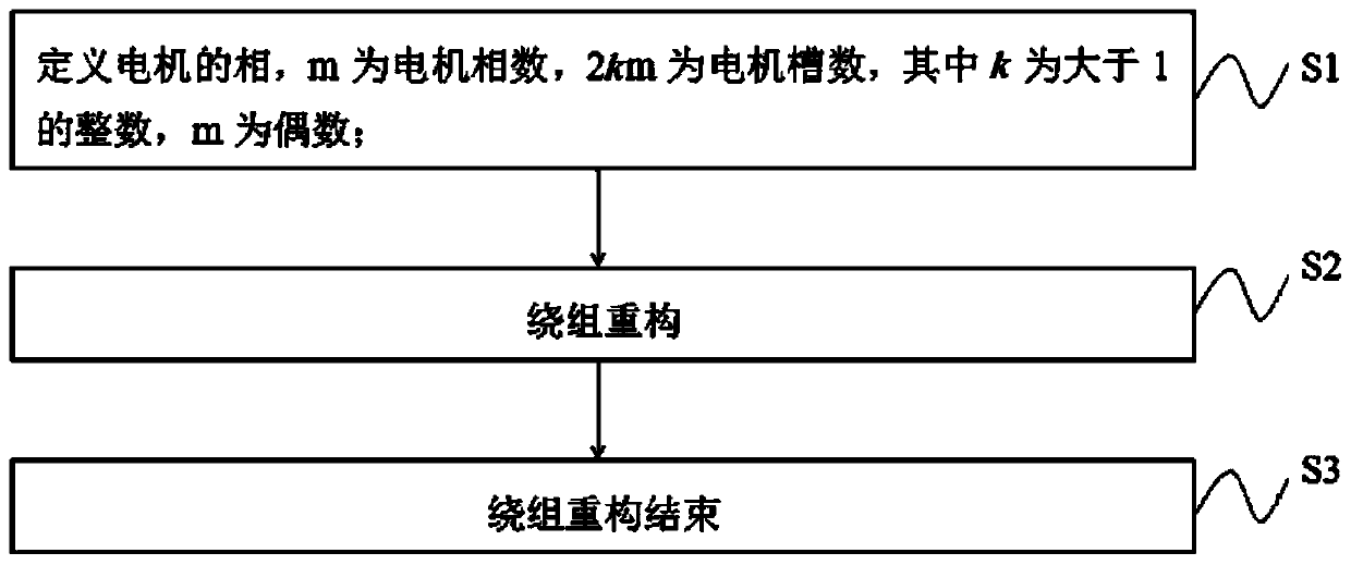
[0048] 36-slot 30-pole forward winding double Y-shift 60° symmetrical six-phase permanent magnet fault-tolerant rim propulsion motor

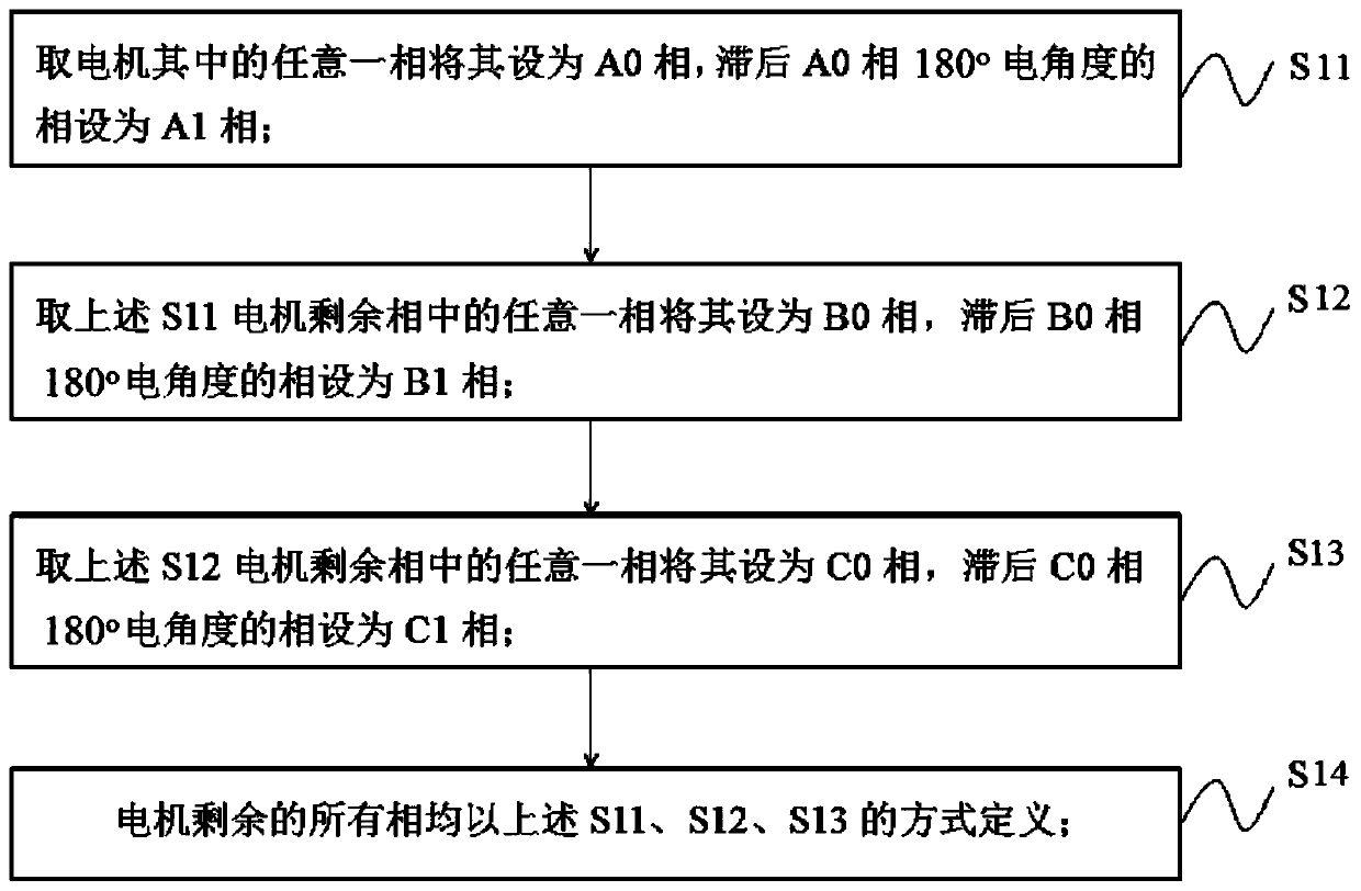
[0049] The winding structure before reconstruction is as Figure 4 As shown, the six-phase windings are A, B, C, U, V, W respectively. Take the winding of phase A as a reference, set it as phase A0, and the phase lagging behind phase A by 180° in electrical angle is phase V and set it as phase A1.

[0050] For the remaining phases B, C, U, and W, take phase B as a reference and set it as phase B0, and the phase that lags phase B by 180° in electrical angle is phase W and set it as phase B1.

[0051] For the remaining C and U phases, take the C phase as a reference and set it as the C0 phase, and the U phase that lags the C phase by 180° electrical angle is the U phase and set it as the C1 phase. All phase definitions are complete.

[0052] The number of motor slots is 2km, that is, 36 slots, where m is 6, and k is 3.

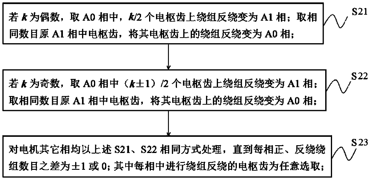
[0053] k is an odd numb...

Embodiment 2

[0061] 48-slot 40-pole forward winding double Y-shift 60° symmetrical six-phase permanent magnet fault-tolerant rim propulsion motor:

[0062] Restructure the front winding structure as Figure 9 As shown, the six-phase windings are A, B, C, U, V, W respectively. Take the winding of phase A as a reference, set it as phase A0, and the phase lagging behind phase A by 180° in electrical angle is phase V and set it as phase A1.

[0063] For the remaining phases B, C, U, and W, take phase B as a reference and set it as phase B0, and the phase that lags phase B by 180° in electrical angle is phase W and set it as phase B1.

[0064] For the remaining C and U phases, take the C phase as a reference and set it as the C0 phase, and the U phase that lags the C phase by 180° electrical angle is the U phase and set it as the C1 phase. All phase definitions are complete.

[0065] The number of motor slots is 2km, that is, 48 ​​slots, where m is 6, and k is 4.

[0066] k is an even numbe...


PUM


Abstract

The invention provides a winding reconstruction method for a permanent-magnet fault-tolerant rim stepping motor to reduce mutual inductance. The winding reconstruction method comprises the steps of S1, defining a motor phase, wherein m is motor phase number, 2km is motor groove number, k is an integer larger than 1, and m is an even number; S2, performing winding reconstruction on the defined motor phase; and S3, ending winding reconstruction. According to the winding reconstruction method for the permanent-magnet fault-tolerant rim stepping motor to reduce mutual inductance, winding reconstruction can be performed on an arbitrary permanent-magnet fault-tolerant rim stepping motor with 2km grooves to reduce the mutual inductance, k is the integer larger than 1, m is the even number, the self-inductance of a winding is improved, the mutual inductance of a 36-groove and 30-pole symmetric six-phase permanent-fault rib stepping motor is reduced, moreover, the beneficial influence of improving the self-inductance of the winding is only caused, and no influence on other motor performance parameters such as on-load counter electromotive force and magnetomotive force harmonic distortion rate is generated.

Description

technical field [0001] The invention relates to a permanent magnet fault-tolerant rim propulsion motor for an integrated motor propeller, in particular to a winding reconfiguration method for a permanent magnet fault-tolerant rim propulsion motor with reduced mutual inductance. Background technique [0002] In order to improve the fault-tolerant performance of the permanent magnet fault-tolerant rim propulsion motor and the ability to limit the short-circuit current, it is required that each phase winding of the motor has a unit inductance, and each phase has a low mutual inductance. [0003] Patent document CN201711029288 discloses a permanent magnet fault-tolerant rim propulsion motor for an integrated motor propeller. The motor includes a stator core, stator slots, armature teeth, isolation teeth, armature windings, an air gap, a magnetic pole protection sleeve, and a magnetic pole protection layer. , Centrifugal permanent magnet, rotor core, propeller welded inside the r...

Claims


Application Information

Patent Timeline
Patent Type & Authority Patents(China)
IPC IPC(8): H02K3/28
CPCH02K3/28
Inventor 朱景伟马瑞于超杨博涵林乾宏
Owner DALIAN MARITIME UNIVERSITY
Why Eureka
Try Eureka