
A compact multi-band antenna

A multi-band antenna, compact technology, applied in the direction of antenna, antenna grounding device, antenna grounding switch structure connection, etc., can solve the problems of difficult integration, narrow frequency band bandwidth, affecting antenna performance, etc., to meet broadband and multi-band, easy Integrated, small size effect

Active Publication Date: 2021-07-16
HARBIN ENG UNIV
View PDF9 Cites 0 Cited by
  • Summary
  • Abstract
  • Description
  • Claims
  • Application Information

AI Technical Summary

Problems solved by technology

[0005] Problem 1: If the antenna is composed of multiple antenna elements, the coupling between the antenna elements affects the performance of the antenna, and the antenna has a large size, which is not easy to integrate. At present, there are few studies on compact antennas;
[0006] Problem 2: The impedance matching of the antenna is poor, and only dual-band can be realized, and the bandwidth of the frequency band is narrow

Method used


Image

  • A compact multi-band antenna
  • A compact multi-band antenna
  • A compact multi-band antenna

Examples


Embodiment Construction

[0028] The present invention will be further described below in conjunction with the accompanying drawings.

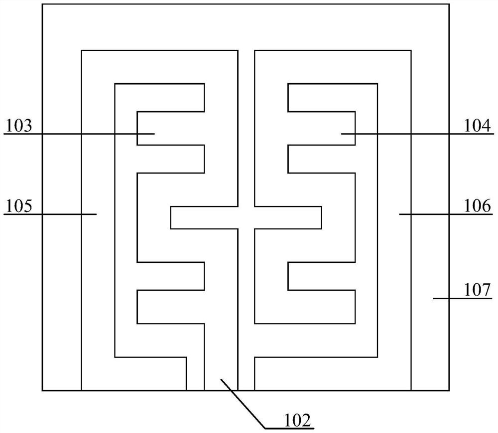
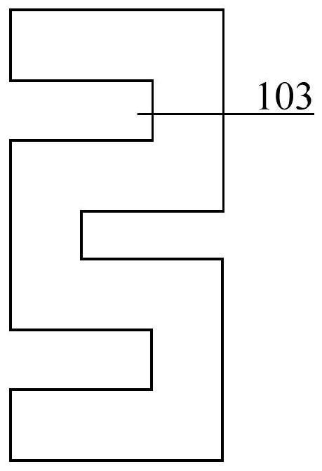
[0029] The present invention provides a compact multi-band antenna, including a dielectric substrate 107, a microstrip transmission line 102 disposed on the dielectric substrate 107, a first bow-shaped radiation unit 103, a second anti-bow-shaped radiation unit 104, and a third C-shaped radiation unit 105 and the fourth anti-C-shaped radiation unit 106 , and part of the ground plane 101 disposed on the back of the dielectric substrate 107 . The first bow-shaped radiation unit 103 and the second anti-bow-shaped radiation unit 104 are formed by bending a rectangular microstrip line multiple times, the first bow-shaped radiation unit 103 is directly connected to the microstrip transmission line 102 for feeding, and the third C-shaped radiation unit 105 is connected to the The first bow-shaped radiation unit 103 is directly connected to feed power. The second anti-bow rad...


PUM


Abstract

The invention belongs to the field of wireless mobile communication, and in particular relates to a compact multi-band antenna. The invention consists of a dielectric substrate, a microstrip transmission line, a first bow-shaped radiation unit, a second anti-shaped radiation unit, a third C-shaped radiation unit, a fourth anti-C-shaped radiation unit, and a ground plane. The first bow-shaped radiating unit and the second anti-C-shaped radiating unit adopt a bow-shaped multi-bending structure, and the third C-shaped radiating unit and the fourth anti-C-shaped radiating unit adopt a C-shaped bending structure. The invention adopts microstrip transmission line feeding, the radiating unit adopts the combination of direct feeding and indirect feeding, adopts multiple bending symmetrical structure and multi-unit integrated design, and realizes the multi-band and miniaturized design of the antenna , the compact multi-band antenna designed by the present invention has the characteristics of low profile, small size, low cost, easy integration, and loadable reactance elements, etc., and can be widely used in various wireless mobile communication devices.

Description

technical field [0001] The invention belongs to the field of wireless mobile communication, and in particular relates to a compact multi-band antenna. Background technique [0002] With the gradual improvement of people's living standards, the dependence on electronic products is becoming stronger and stronger, and mobile communication devices such as mobile phones, computers, and tablet computers are more and more widely used in people's daily life. And with the advancement of technology and the more stable and mature manufacturing process, the miniaturization of mobile communication equipment has become a development trend, and higher requirements have been proposed for antennas that connect the internal components of mobile communication equipment with the external environment. Requirements, the development of miniaturization, integration, broadband, multi-band and other directions will be the trend of antenna design in the future. In wireless mobile communication system...

Claims


Application Information

Patent Timeline
Patent Type & Authority Patents(China)
IPC IPC(8): H01Q1/38H01Q1/48H01Q1/50H01Q5/20
CPCH01Q1/38H01Q1/48H01Q1/50H01Q5/20
Inventor 李迎松董玥孙来军西尼吉维奇·耶夫基尼马尔达乔夫·费拉基米尔·伊万诺奇
Owner HARBIN ENG UNIV
Learn More