
Method for monitoring leakage at joints of underground diaphragm wall

A technology for underground diaphragm walls and joints, which can be used in directions such as detecting the presence of fluid at leak points, testing fluid tightness with electrical devices, and measuring liquid tightness with liquid/vacuum degrees. The impact of stable use, the inability to monitor the leakage of underground diaphragm walls, and the low detection accuracy and accuracy have achieved the effects of increasing detection accuracy and accuracy, reducing construction costs, and improving excavation safety.

Inactive Publication Date: 2018-11-20
CHINA UNIV OF MINING & TECH
View PDF6 Cites 8 Cited by
  • Summary
  • Abstract
  • Description
  • Claims
  • Application Information

AI Technical Summary

Problems solved by technology

At present, the main detection methods used in the industry are ultrasonic method and resistivity method. These methods need to cause damage to the underground diaphragm wall during detection, such as drilling, which will affect the subsequent stable use of the underground diaphragm wall after detection. In addition, the above-mentioned methods cannot be close to the joint where leakage is most likely to occur during detection, so the detection accuracy and accuracy are low; at the same time, the above-mentioned two methods are limited by their current on-site construction layout, and cannot be detected after the construction is completed. Diaphragm Wall for Long-Term Leakage Monitoring

Method used


Image

  • Method for monitoring leakage at joints of underground diaphragm wall
  • Method for monitoring leakage at joints of underground diaphragm wall
  • Method for monitoring leakage at joints of underground diaphragm wall

Examples

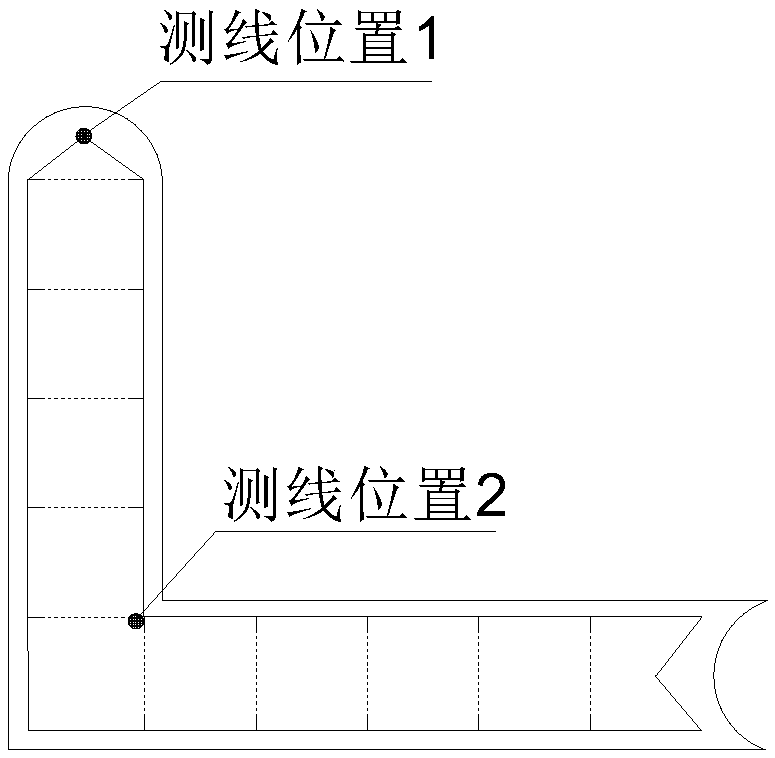
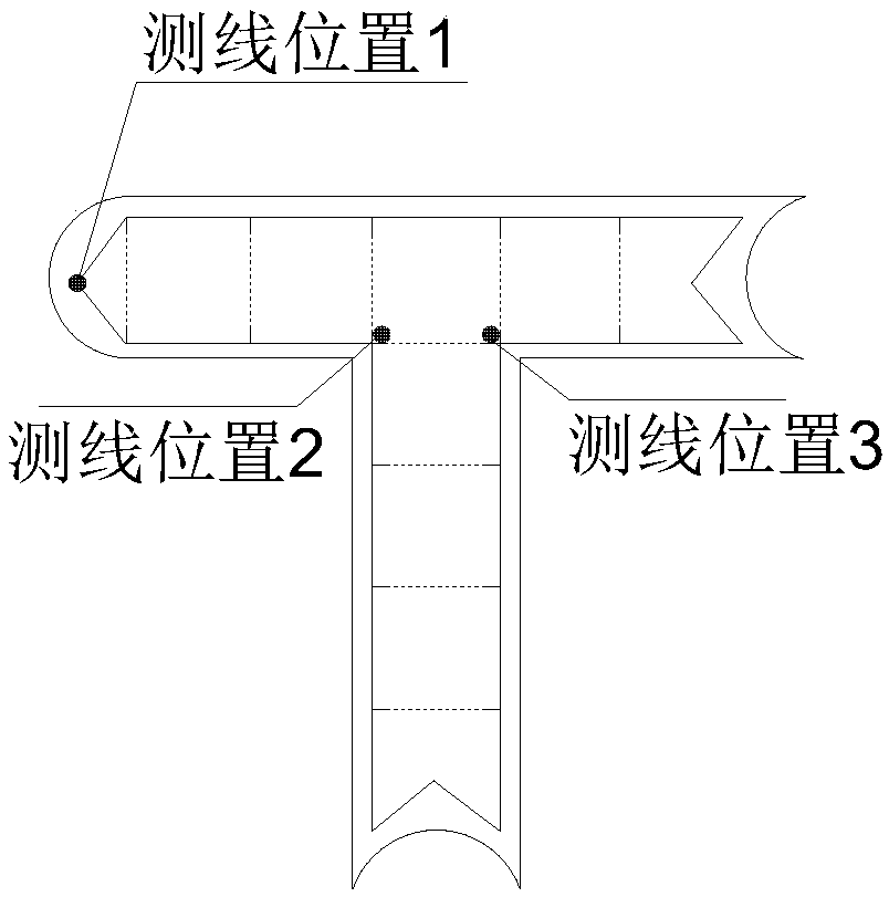

Embodiment Construction

[0023] The present invention will be further explained below.

[0024] Such as Figure 1 to Figure 5 As shown, the specific steps of the present invention are:

[0025] A. Determine the shape of the reinforcement cage of the diaphragm wall according to the construction type of the diaphragm wall, and then lay out electrode measuring lines at the joints and corners of the diaphragm wall;

[0026] B. Each electrode measuring line is laid longitudinally along the underground continuous wall at the laying position, and the electrode measuring line is fixed on the steel cage of the underground continuous wall by insulating tape;

[0027] C. Set up 48 electrode measurement points on each electrode survey line, and the distance between adjacent electrode survey points on part of the electrode survey line in the aquifer is 0.25m, and the remaining part of the electrode survey line is adjacent The distance between the electrode measuring points is 0.5m; the electrode measuring line used is co...


PUM


Abstract

The invention discloses a method for monitoring leakage at the joints of an underground diaphragm wall. Based on the steel cage structure of the underground diaphragm wall, electrode measuring lines are arranged in the underground diaphragm wall; each electrode measuring line is provided with a plurality of electrode measuring points; and the leakage of the underground diaphragm wall is monitoredthrough adopting a natural potential method. With the method of the invention adopted, construction can be convenient; drilling is not required; construction costs can be decreased; no damage is caused to the wall; the measuring points are close to leakage point positions, so that detection accuracy and accuracy can be improved; the leakage at the joints of the underground diaphragm wall can be positioned; the leakage condition of the underground diaphragm wall can be continuously monitored in the later stage; technical blank in arranging electrodes in the underground diaphragm wall and applying the natural potential method to detect and monitor the leakage positions of the underground diaphragm wall can be filled; and great guidance can be provided for the safe excavation of a foundationpit.

Description

Technical field [0001] The invention relates to a method for monitoring an underground continuous wall, in particular to a method for monitoring the leakage at the joint of the underground continuous wall. Background technique [0002] Diaphragm walls are widely used in the construction of deep foundation pits in urban high-rise buildings, subways, etc., and have the functions of load-bearing, soil retaining, water interception, and seepage prevention. Therefore, the leakage of diaphragm walls directly affects high-rise buildings, subways, etc. Safety and quality issues. Among them, whether the joint connection (ie, the joint) between the adjacent grooves of the underground continuous wall containing the steel cage is sealed is very important. It is the key position where the underground continuous wall is most likely to leak. If there is mud and sand at the joint, it will As a result, the connection is not firm, and leakage may occur. Therefore, evaluating whether the undergro...

Claims


Application Information

Patent Timeline
Patent Type & Authority Applications(China)
IPC IPC(8): G01M3/04G01M3/40
CPCG01M3/04G01M3/40
Inventor 杨彩刘盛东杨海平
Owner CHINA UNIV OF MINING & TECH
Learn More