Special deicing vehicle for rails

A technology for deicing trucks and rails, which is applied to track cleaning, construction, cleaning methods, etc., and can solve problems such as low cleaning efficiency, easy freezing and snow accumulation on rails, and incomplete cleaning

Pending Publication Date: 2018-11-20
雄县智邦节能设备制造有限公司
View PDF0 Cites 1 Cited by
  • Summary
  • Abstract
  • Description
  • Claims
  • Application Information

AI Technical Summary

Problems solved by technology

[0002] Railways are rails used by vehicles such as trains. Railways have spread all over the country, but in winter, the rails are prone to freezing and snow accumulation. If the snow is relatively large, it will seriously affect the progress of the train. Cart cleaning has low cleaning efficiency. After the ice and snow melt, it is easy to freeze again due to the cold weather, resulting in incomplete cleaning. At the same time, electric heating is used to melt the ice and snow, which causes energy waste during the heat transfer process.

Method used


Image

  • Special deicing vehicle for rails
  • Special deicing vehicle for rails
  • Special deicing vehicle for rails

Examples


Embodiment 1

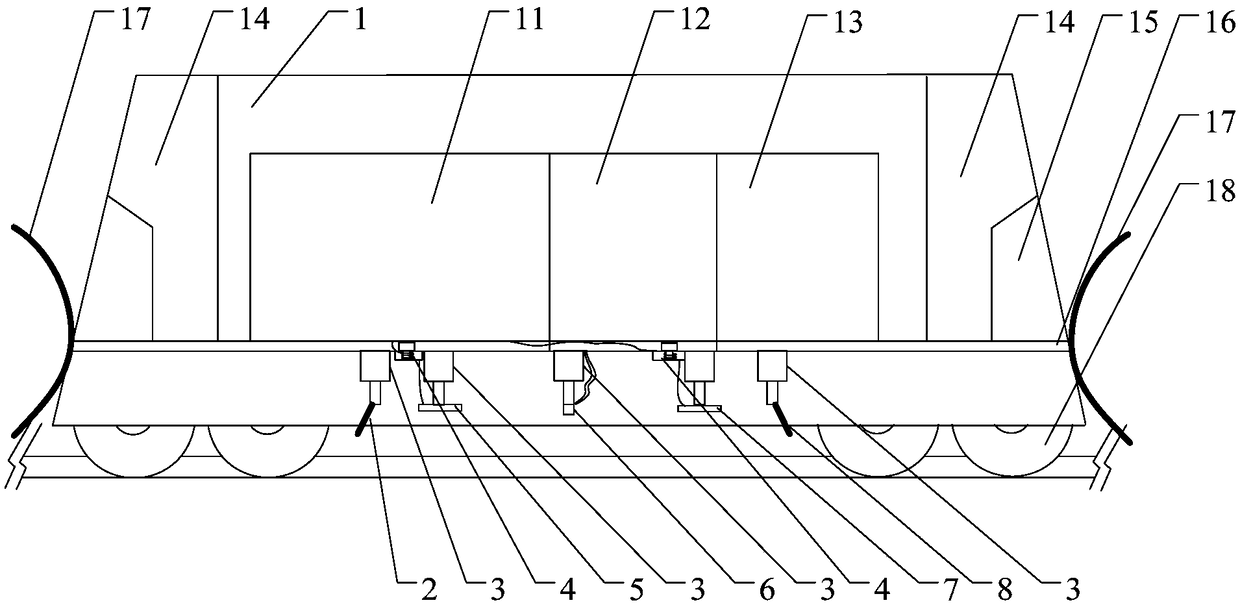
[0019] figure 1 It is a structural schematic diagram of a special deicing vehicle for rails in which the lifting device of the present invention is a plurality of telescopic cylinders, as figure 1 As shown, a rail-specific deicing vehicle includes a car body 1, and push buckets 17 are fixed at both ends of the car body 1, and when the snow accumulation is large, the upper layer of snow is pushed to both sides of the rail 9 by the push bucket 17. Both ends of the car body 1 are provided with a control room 14, and a console 15 is provided in the control room 14 for controlling the lifting and starting and stopping of the deicing mechanism. The inside of the car body 1 is provided with a power distribution room 13, a high-pressure air pump room 12, and an electromagnetic heating device room 11. A deicing mechanism is fixed below the chassis 16 of the car body 1. Two deicing mechanisms are arranged in parallel. The deicing mechanism and the rail 9 Relatively, a lifting device is...

Embodiment 2

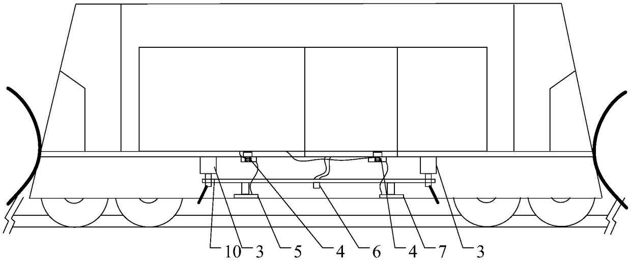
[0022] figure 2 It is a structural schematic diagram of a rail-specific deicing vehicle with a fixed plate in the lifting device of the present invention. The difference between this embodiment and Embodiment 1 is that the lifting device includes a fixed plate 10 and telescopic cylinders 3 arranged at both ends of the fixed plate 10. The first deicing The ice shovel 2, the first heating plate 5, the high-pressure nozzle 6, the second heating plate 7 and the second deicing shovel 8 are all fixed on the fixed plate, realizing the first deicing shovel 1, the first heating plate 5, the high pressure The blowing nozzle 6, the second heating plate 7 and the second deicing blade 8 are lifted and lowered simultaneously.

[0023] Therefore, the present invention adopts a special deicing vehicle for railroad tracks with the above-mentioned structure, and the deicing is cleaner, and the principle of electromagnetic induction is used to make the rails self-heating, so that the ice and sn...


PUM


Abstract

The invention discloses a special deicing vehicle for rails. The deicing vehicle comprises a vehicle body, control rooms are arranged at both ends of the vehicle body, and a power distribution room, ahigh-pressure air pump room and an electromagnetic heating device room are arranged in the vehicle body; two deicing mechanisms are opposite to the rails and are parallelly fixed to the lower portionof a chassis of the vehicle body and provided with lifting devices, and each deicing mechanism includes a first deicing shovel, a first heating disc, a high-pressure blowing nozzle, a second heatingdisc and a second deicing shovel; the first heating discs and the second heating discs are connected to the electromagnetic heating device room, and the high-pressure blowing nozzles are connected toa high-pressure air pump of the high-pressure air pump room. According to the special deicing vehicle for the rails, by adopting the structure above, deicing is conducted more thoroughly; moreover, the rails are automatically heated according to an electromagnetic induction principle, so that ice and snow are melt more effectively, then ice water is removed through the high-pressure blowing nozzles to prevent secondary icing, the ice and water are removed thoroughly through secondary heating, and the deicing efficiency is high.

Description

technical field [0001] The invention relates to the technical field of railway cleaning machinery, in particular to a special deicing vehicle for railway tracks. Background technique [0002] Railways are rails used by vehicles such as trains. Railways have spread all over the country, but in winter, the rails are prone to freezing and snow accumulation. If the snow is relatively large, it will seriously affect the progress of the train. Cart cleaning has low cleaning efficiency. After the ice and snow melt, it is easy to freeze again due to the cold weather, resulting in incomplete cleaning. At the same time, electric heating is used to melt the ice and snow, which causes energy waste in the process of heat transfer. Contents of the invention [0003] The purpose of the present invention is to provide a special deicing vehicle for railroad tracks, which is cleaner in deicing, and adopts the principle of electromagnetic induction to make the rails self-heating, thereby mor...

Claims


Application Information

Patent Timeline
Patent Type & Authority Applications(China)
IPC IPC(8): E01H8/08
CPCE01H8/08
Inventor 刘平
Owner 雄县智邦节能设备制造有限公司
Why Eureka
Try Eureka