
Equipment and method for internal high-pressure formation of high-plastic steel pipes

A technology of internal high-pressure forming and steel pipes, which is applied in the field of steel pipe quenching, can solve problems such as multiple scales and the influence of steel pipe structural strength, and achieve the effect of good structural strength of steel pipes

Active Publication Date: 2018-11-20
江阴市一鸣管业科技有限公司
View PDF8 Cites 1 Cited by
  • Summary
  • Abstract
  • Description
  • Claims
  • Application Information

AI Technical Summary

Problems solved by technology

[0003] The current steel pipe quenching, the general process is to heat the steel pipe and then directly cool it, but the surface of the steel pipe produced in this way will produce more scale, which will affect the structural strength of the steel pipe

Method used


Image

  • Equipment and method for internal high-pressure formation of high-plastic steel pipes
  • Equipment and method for internal high-pressure formation of high-plastic steel pipes
  • Equipment and method for internal high-pressure formation of high-plastic steel pipes

Examples


Embodiment 1

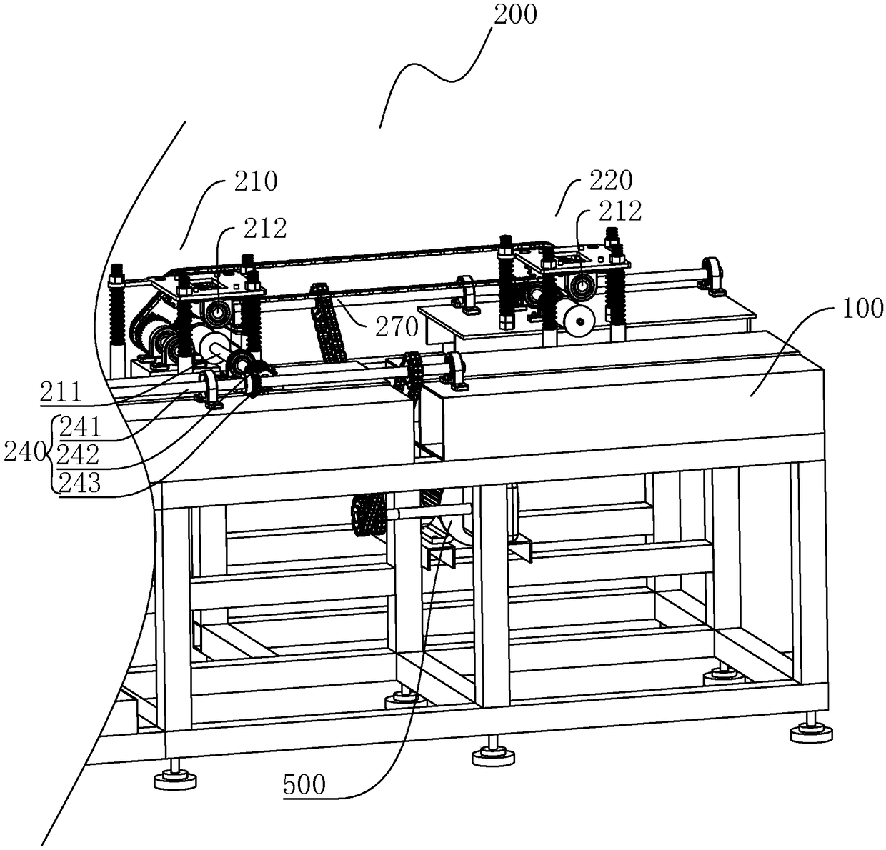
[0045] Embodiment 1: A kind of equipment for internal high pressure forming high plastic steel pipe, such as figure 1 As shown, the walking frame 100 is included, and the walking frame 100 is provided with an intermediate frequency induction heater 300, a heat preservation device 600, and a cooling device 400 in sequence along the advancing direction of the steel pipe.

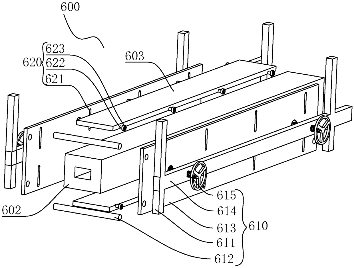
[0046] Such as figure 1 and 2As shown, the heat preservation device 600 includes a heat preservation support 601 and a heat preservation layer 602 arranged on the heat preservation support 601 , and a square through hole for passing through a square steel pipe is opened in the heat preservation layer 602 . The thermal insulation layer 602 is made of thermal insulation cotton, and the thermal insulation bracket 601 is provided with a first adjusting component 610 for adjusting the size of the through hole. After the steel pipe is heated by the medium frequency induction heater 300, it enters the square throug...

Embodiment 2

[0067] Embodiment 2: A kind of equipment for internal high pressure forming high plastic steel pipe, such as figure 1 and 6 As shown, the thermal insulation layer 602 is made of thermal insulation cotton, and the cross-section of the through hole is arranged in a circle. The thermal insulation bracket 601 is provided with a third adjustment component 630 for adjusting the diameter of the through hole. In this embodiment, the through hole is set in a circular shape, which is mainly suitable for circular steel pipes. When processing steel pipes of different sizes, the thermal insulation cotton is more suitable for the circular steel pipes during adjustment.

[0068] Such as Figure 6 As shown, the third adjustment assembly 630 includes two semicircular hoops 631 arranged up and down, the insulation layer 602 is located between the two hoops 631, the two sides of the heat preservation bracket 601 are respectively provided with adjustment plates 632, and the adjustment plates 632...


PUM


Abstract

The invention discloses equipment for internal high-pressure formation of high-plastic steel pipes, and belongs to the field of steel pipe quenching; and the equipment for internal high-pressure formation of the high-plastic steel pipes reduces scales on the surfaces of steel pipes. The equipment comprises a travelling bracket; a medium-frequency induction heater and a cooling device are arrangedon the travelling bracket in a steel pipe advancing direction in sequence; the travelling bracket is provided with a travelling device for driving the steel pipes to advance; an insulation device is arranged between the medium-frequency induction heater and the cooling device; the insulation device comprises an insulation bracket, and an insulation layer arranged on the insulation bracket; and through holes for enabling the steel pipes to pass through are formed in the insulation layer. As the insulation device is arranged between the medium-frequency induction heater and the cooling device, the scales on the surfaces of the produced steel pipes are few, and the structural strength of the steel pipes is higher.

Description

technical field [0001] The invention relates to the field of steel pipe quenching, in particular to an equipment and method for forming high-plastic steel pipes by internal high pressure. Background technique [0002] In the steel pipe production process, it is necessary to quench the steel pipe and heat the steel to the critical temperature Ac 3 (hypoeutectoid steel) or Ac 1 (Hypereutectoid steel) above the temperature, keep it warm for a period of time to make it fully or partially austenitized, and then quickly cool it below Ms (or isothermal near Ms) at a cooling rate greater than the critical cooling rate to undergo martensite (or bainite) body) transformation. [0003] The current steel pipe quenching, the general process is to heat the steel pipe and then directly cool it, but the surface of the steel pipe produced in this way will produce more oxide skin, which will affect the structural strength of the steel pipe. Contents of the invention [0004] The first ob...

Claims


Application Information

Patent Timeline
Patent Type & Authority Applications(China)
IPC IPC(8): C21D9/08C21D1/62
CPCC21D1/62C21D9/085
Inventor 单嘉诚
Owner 江阴市一鸣管业科技有限公司
Learn More