Eureka AIR delivers breakthrough ideas for toughest innovation challenges, trusted by R&D personnel around the world.

Floor drain connecting device and construction method thereof

A connecting device and floor drain technology, which is applied to water supply devices, building components, drainage structures, etc., can solve problems such as the influence of anti-leakage work, the long time span of floor drain installation, and the large investment in inspection and acceptance manpower, so as to reduce the inspection and acceptance manpower, The effect of long installation time span and shortened construction period

Inactive Publication Date: 2018-11-16
SHANDONG PINGAN CONSTR GROUP
View PDF10 Cites 2 Cited by
  • Summary
  • Abstract
  • Description
  • Claims
  • Application Information

AI Technical Summary

Problems solved by technology

[0004] 1. The construction cost is relatively high: because the existing technology requires the use of pre-embedded hole-forming molds in the early stage of the project, the hanging and plugging molds during the second pouring, and the material costs of the floor drain body components are high
[0005] 2. Long construction period: Because the existing technology needs to set reserved holes, clean reserved holes, and secondary pouring, the waiting time between these three steps is long, which is the most time-consuming part of the overall construction. The multiple verification of the elevation during the secondary pouring process makes the installation time span of the floor drain in the prior art long and the construction period is long
[0006] 3. Large manpower input for inspection and acceptance: In the construction of floor drains in the prior art, each step in the construction needs to be inspected and accepted, which requires a lot of waste of manpower to complete the inspection work, which increases the human resources of this part
[0007] 4. It is difficult to control the quality of appearance and the effect of use: because in the construction of the floor drain of the prior art, it is necessary to repeatedly check the elevation during the steps from setting the reserved hole to the hanging formwork. Once the elevation measurement is wrong, it will directly affect the appearance quality; moreover, there are too many steps in the construction of the floor drain, and if one step is not handled properly, it will have an impact on the anti-leakage work

Method used


Image

  • Floor drain connecting device and construction method thereof
  • Floor drain connecting device and construction method thereof
  • Floor drain connecting device and construction method thereof

Examples


Embodiment 1

[0042] The installation of the floor drain in the prior art includes the following steps:

[0043] (1) Positioning: After hoisting the template, mark the installation position of the floor drain on the template and check whether the positioning is accurate;

[0044] (2) Reserved holes: mark the position of the floor drain on the formwork, fix the pre-embedded hole-forming mold on the formwork with nails, and bind the steel frame of the floor at the same time. Pour them together to form a reinforced concrete floor slab 7, and check the reserved holes;

[0045] (3) Clean up the reserved holes: after the reinforced concrete floor slab 7 is formed, take off the pre-embedded hole-forming mold, clean up the chiseled hairs of the reserved holes, and check the cleaning situation of the reserved holes;

[0046] (4) Install the floor drain connection pipe: After verifying the floor drain elevation, install the floor drain connection pipe at the reserved hole, and check the floor drain ...

Embodiment 2

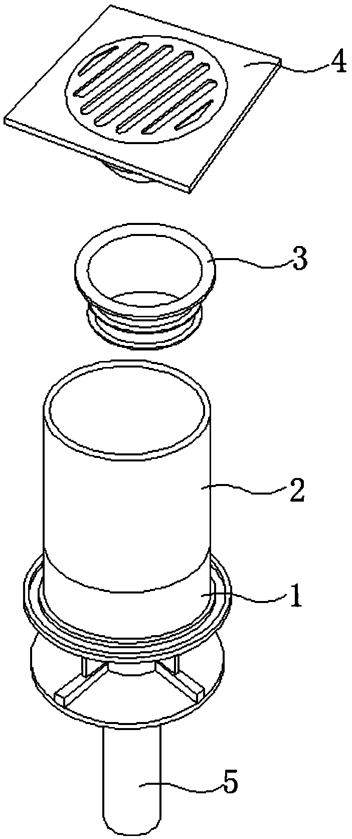
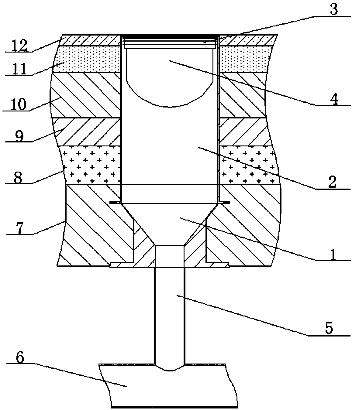
[0055] A floor drain connection device such as figure 1 and figure 2 As shown, it includes the water stop section 1 fixed on the formwork and poured together with the formwork and the floor steel frame. The water stop section 1 passes through the floor. The upper part of the water stop section 1 communicates with the drain pipe 2, and the upper part of the drain pipe 2 connects with the floor drain The body 4 is connected. The floor slab is hoisted according to the design drawings during the project, and the floor slab is used to locate the water stop section 1.

[0056] Further, the upper part of the drain pipe 2 is connected to the floor drain body 4 through a sealing rubber pad 3, specifically, the sealing rubber pad 3 is an annular rubber pad.

[0057] Further, the lower part of the water stop section 1 communicates with the downspout 5 .

[0058] Further, the water stop section 1 is connected to the drain pipe 2 through a sealant, and the water stop section 1 is conne...

Embodiment 3

[0071] The comparison between Embodiment 1 and Embodiment 2 in terms of process, time, cost, perception and use effect is shown in Table 1:

[0072] The comparative table of table 1 embodiment 1 and embodiment 2

[0073]

[0074]

[0075]

[0076] According to the above table, the specific analysis is as follows:


PUM


Abstract

The invention discloses a floor drain connecting device and a construction method thereof, and belongs to the technical field of floor drain construction. The floor drain connecting device comprises awater stopping node which is fixed to a template and is poured together with the template and a floor slab reinforced concrete frame; the water stopping node penetrates a floor slab; the upper side of the water stopping node communicates with a drainage pipe; and the upper side of the drainage pipe is connected to a floor drain amin body. The construction method comprises the following construction steps: (1) conducting locating; (2) burying the water stopping node; (3) mounting the drainage pipe; (4) conducting waterproofing treatment; (5) paving a ground; (6) mounting a floor drain; (7) mounting a water-falling pipe; and (8) implementing a test. The floor drain connecting device and the construction method provided by the invention can reduce construction cost, shorten a construction period, reduce human input in inspection and acceptance, and reduce appearance quality and control difficulty of a using effect.

Description

technical field [0001] The invention relates to the technical field of floor drain construction, in particular to a floor drain connection device and a construction method thereof. Background technique [0002] The installation method of the floor drain, the prior art includes the reserved hole of the embedded part; the reserved hole is cleaned and chiseled, the floor drain is connected to the pipeline, and the pipeline passes through the top plate to cover the water stop ring. After strict floor drain elevation calculation, install the floor drain in place; reserve a hole for secondary pouring, check the floor drain elevation before and after the secondary pouring period, check the quality of the hanging plugging and carry out waterproofing steps after the plugging is completed; install the floor drain later and other steps. [0003] The problems of prior art are as follows: [0004] 1. High construction cost: because the existing technology requires the use of pre-embedd...

Claims


Application Information

Patent Timeline
Patent Type & Authority Applications(China)
IPC IPC(8): E03F5/04E04B1/38E04B1/66E04G21/00
CPCE03F5/04E04B1/38E04B1/66E04G21/00
Inventor 李华磊高扬袁坤史岐山刘海兰宫收强孙凤丽华瑾邹燕燕孙宇航
Owner SHANDONG PINGAN CONSTR GROUP
Why Eureka
Eureka Blog
Learn More