Underwater working device and method
A technology of working device and working platform, applied in water conservancy projects, underwater structures, artificial islands, etc., can solve the problems of poor wind and wave resistance, long construction period, inconvenient movement, etc., and achieve strong wind and wave resistance and construction period. Short, easy to install and remove
- Summary
- Abstract
- Description
- Claims
- Application Information
AI Technical Summary
Problems solved by technology
Method used
Image

Examples
Embodiment 1
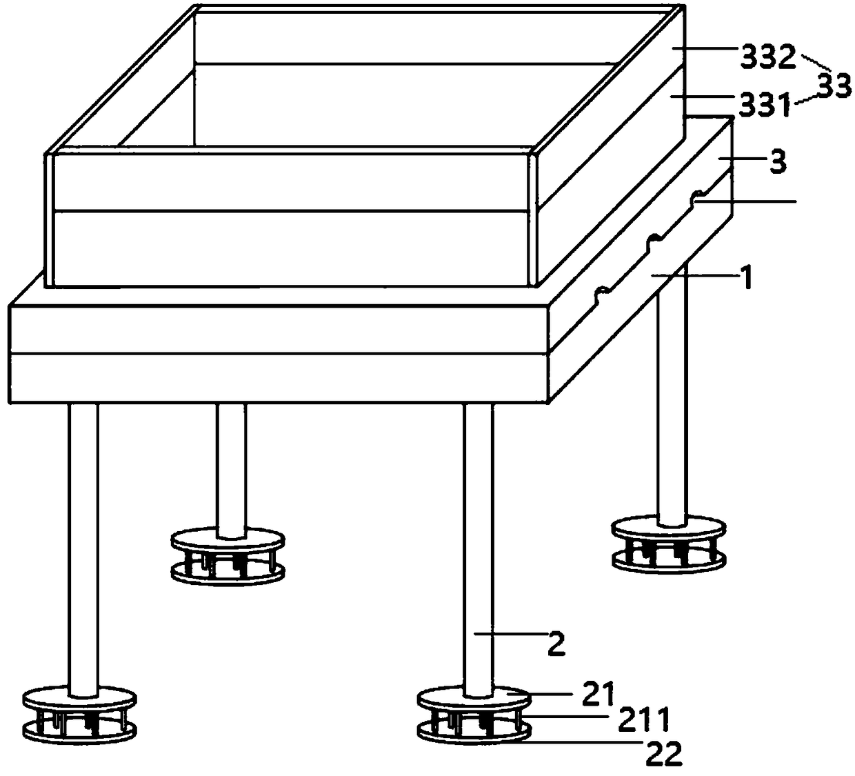
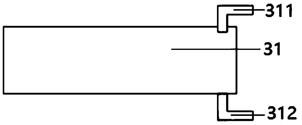
[0052] like figure 1 , figure 2 , Figure 5 The shown embodiment is a kind of underwater operation device, comprising a support frame 1, four support piles 2 arranged at the lower part of the support frame, and a work platform 3 arranged on the support frame; a ballast water tank 31 is arranged in the work platform, and A water inlet pipe 311 and an outlet pipe 312 are arranged on the water tank, a water pump 35 and a vacuum pump 36 are arranged on the water inlet pipe, a solenoid valve 3011 is arranged on the water inlet pipe and the water outlet pipe, and a controller 4 on the work platform is also included to support There are 4 driving devices 9 for driving the support pile to move up and down and a lifting device 10 for driving the platform to move up and down on the frame, and the controller is electrically connected with 2 solenoid valves, water pumps, vacuum pumps, each driving device and the lifting device .
[0053] like figure 1 As shown, the lower end of each ...
Embodiment 2
[0070] Embodiment 2 comprises all structures and method parts in embodiment 1, as figure 1 As shown, the working platform of Embodiment 2 is rectangular, and windshields 33 are arranged on the 4 edges of the working platform, and each windshield includes a lower rectangular plate 331 and an upper rectangular plate 332, and each windshield Both the lower rectangular plate and the upper rectangular plate are connected by a rotating shaft, and each rotating shaft is provided with a rotating motor 334 for driving the upper rectangular plate to rotate along the lower rectangular plate, such as Figure 5 As shown, each rotating motor is electrically connected to the controller. Also include the following steps:
[0071] (8-1) The operator obtains the current wind speed data information through the network, and the wind speed threshold is set to K; K is 10 m / s;
[0072] (8-2) When the wind speed > K, the operator controls the operation of each rotating motor through the controller,...
Embodiment 3
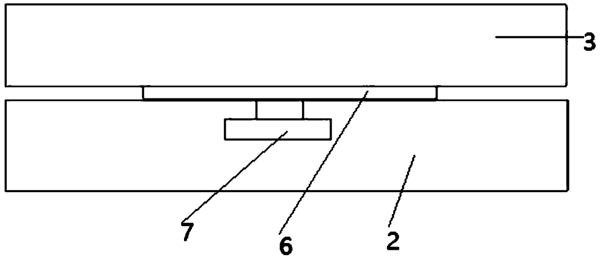
[0076] Embodiment 3 comprises all structures and method parts of embodiment 2, as image 3 , Figure 5 As shown, the working platform of embodiment 3 is provided with wind direction anemometer 5, and the support frame upper surface is provided with turntable 6, and turntable is connected with work platform through lifting device, and support frame is provided with turntable motor 7, and work platform lower surface is provided with There are three parallel diversion grooves 8, and the wind direction anemometer and the turntable motor are electrically connected to the controller.
[0077] Steps (8-1) to (8-3) are replaced by the following steps:
[0078] (9-1) The wind direction anemometer detects the current wind direction and wind speed, and the wind speed threshold is set to K;
[0079] (9-2) When the wind speed > K, the operator controls the operation of each rotating motor through the controller, so that the angle between the upper rectangular plate and the lower rectangu...
PUM
 Abstract
Description
Claims
Application Information
 - Generate Ideas
- Intellectual Property
- Life Sciences
- Materials
- Tech Scout
- Unparalleled Data Quality
- Higher Quality Content
- 60% Fewer Hallucinations
Browse by: Latest US Patents, China's latest patents, Technical Efficacy Thesaurus, Application Domain, Technology Topic, Popular Technical Reports.
© 2025 PatSnap. All rights reserved.Legal|Privacy policy|Modern Slavery Act Transparency Statement|Sitemap|About US| Contact US: help@patsnap.com