
Automatic pipe fitting cutting equipment

A technology for automatic cutting and pipe fittings, applied in metal processing equipment, metal processing machinery parts, clamping, etc., can solve the problems of low work efficiency, high labor cost, and low degree of automation, and achieve the goal of improving work efficiency and saving labor costs Effect

Inactive Publication Date: 2018-11-16
ZHANGJIAGANG INST OF IND TECH SOOCHOW UNIV +1
View PDF5 Cites 8 Cited by
  • Summary
  • Abstract
  • Description
  • Claims
  • Application Information

AI Technical Summary

Problems solved by technology

The existing pipe fitting cutting equipment cannot fix the steel pipe conveniently and securely, and the high-temperature waste generated when cutting the steel pipe will pose a serious threat to the worker's body, especially the eyes
At the same time, due to the unreliable fixation of the steel pipe, there is a hidden danger that the steel pipe will be separated from the pipe fitting cutting equipment when cutting the steel pipe, which poses a serious threat to the life and health of workers
[0004] In addition, most of the existing pipe cutting equipment requires manual assistance, and the degree of automation is relatively low, resulting in high labor costs and low work efficiency.

Method used


Image

  • Automatic pipe fitting cutting equipment
  • Automatic pipe fitting cutting equipment
  • Automatic pipe fitting cutting equipment

Examples


Embodiment Construction

[0039] The technical solution of the present invention will be described in further non-limiting detail below in combination with preferred embodiments and accompanying drawings.

[0040] In describing the present invention, it is to be understood that the terms "upper", "lower", "front", "rear", "left", "right", "vertical", "horizontal", "top", The orientation or positional relationship indicated by "bottom", "inner", "outer", etc. are based on the orientation or positional relationship shown in the drawings, and are only for the convenience of describing the present invention, rather than indicating or implying that the referred device or element must be Having a particular orientation, or being constructed and operative in a particular orientation, should therefore not be construed as limiting the invention.

[0041] In the present invention, terms such as "installation", "connection", "connection", "fixation" and "setting" should be interpreted in a broad sense, for exampl...


PUM


Abstract

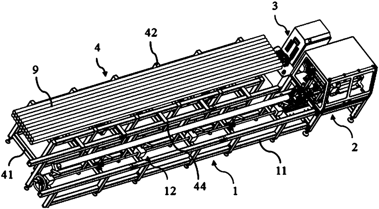
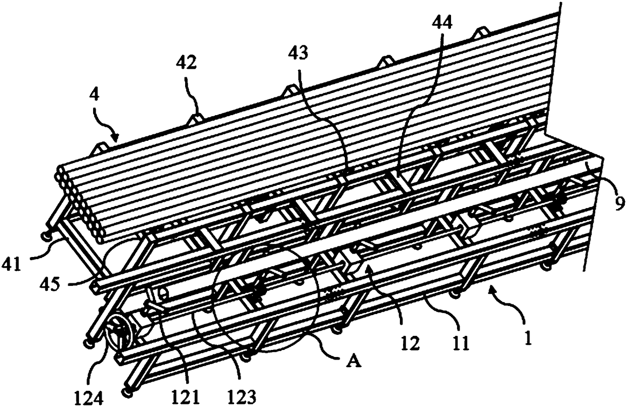
The invention discloses automatic pipe fitting cutting equipment. The equipment comprises a delivery mechanism, a machining mechanism and a control mechanism; the delivery mechanism comprises a support, a liftable support mechanism is installed on the upper portion of the support, the machining mechanism comprises a clamping mechanism, a pressing mechanism, a cutting mechanism and a limiting mechanism, the clamping mechanism is arranged at one end of the support, the pressing mechanism, the cutting mechanism and the limiting mechanism are sequentially arranged on a rack, the clamping mechanismand the pressing mechanism are used for fixing and clamping a pipe fitting, the limiting mechanism is used for determining the position of the pipe fitting, and the control mechanism is electricallyconnected with the machining mechanism. According to the automatic pipe fitting cutting equipment, by means of mutual cooperation of the loading mechanism, the delivery mechanism, the machining mechanism and the control mechanism, full-automatic operation of loading, clamping fixing, cutting and discharging of the pipe fitting is achieved, the phenomena that high-temperature scraps are generated in the pipe fitting cutting process, pipe fitting fixing is not firm and breaks away from the pipe fitting cutting equipment, and potential safety hazards are caused to workers are avoided, the labor cost is greatly reduced, and the work efficiency is improved.

Description

technical field [0001] The invention belongs to the field of mechanical equipment, and in particular relates to an automatic cutting equipment for pipe fittings. Background technique [0002] Steel pipes have a wide range of industrial applications. Since the shape of steel pipes is cylindrical, it is difficult to fix, and there are often inaccurate and uneven cutting surfaces. [0003] Generally, simple cutting machines are easy to operate, and the machine head needs to be manually pressed down to cut the material. Existing pipe fitting cutting equipment cannot fix the steel pipes conveniently and securely, and the high-temperature waste generated when cutting the steel pipes will pose a serious threat to the body of the worker, especially the eyes. Simultaneously, because steel pipe is not fixed firmly, when cutting steel pipe, steel pipe has the hidden danger that breaks away from pipe fitting cutting equipment, constitutes serious threat to worker's life and health. ...

Claims


Application Information

Patent Timeline
Patent Type & Authority Applications(China)
IPC IPC(8): B23Q7/00B23Q3/08
CPCB23Q3/08B23Q7/00
Inventor 陈涛高万里孙立宁
Owner ZHANGJIAGANG INST OF IND TECH SOOCHOW UNIV
Learn More