
A valve casting production line with high safety and automation

A casting production line, safety technology, applied in foundry workshops, casting equipment, casting molding equipment, etc., can solve the problems of internal cleaning of shot blasting and sand cleaning devices, waste of labor time and energy, and affect production efficiency, etc., to reduce temperature, increase production safety, and improve the working environment

Active Publication Date: 2020-02-21
SHENYUE FUJIAN CASTING
View PDF5 Cites 0 Cited by
  • Summary
  • Abstract
  • Description
  • Claims
  • Application Information

AI Technical Summary

Problems solved by technology

In the pouring area of ​​the valve casting production, the casting machine is usually used to cast molten metal into the valve mold plate, but the existing valve casting production line usually uses manual transfer of the valve mold plate to the casting machine for casting and then transported away. A lot of labor time and energy are wasted, the production efficiency is low, and it is inconvenient to use
Moreover, the formed valve castings still need to grind the burrs and protrusions on the valve castings, while the traditional structure used for grinding valve castings is relatively complicated, and the grinding efficiency is low, which seriously affects the production efficiency
In addition, the polished valve castings should be polished in the polishing area. Shot blasting and sand cleaning devices are commonly used in polishing. After a period of use, a large amount of dust and sand will accumulate in the shot blasting and sand cleaning devices. Metal debris, and the interior of the shot blasting and sand cleaning device cannot be effectively cleaned by simple cleaning methods

Method used


Image

  • A valve casting production line with high safety and automation
  • A valve casting production line with high safety and automation
  • A valve casting production line with high safety and automation

Examples


Embodiment Construction

[0069] In order to further explain the technical solution of the present invention, the present invention will be described in detail below through specific examples.

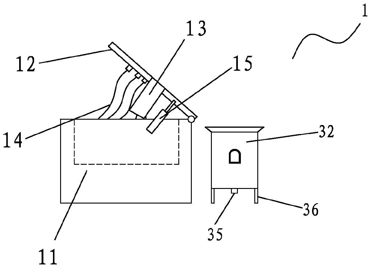
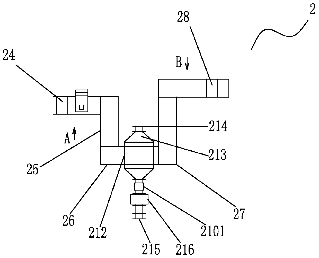
[0070] Such as Figure 1-18 As shown, a valve casting production line with high safety and automation, which includes a metal melting zone 1, a wax molding zone 2, a pouring zone 3, a grinding zone 4 and a polishing zone 5, the metal melting zone 1, wax The material forming area 2, the pouring area 3, the grinding area 4 and the polishing area 5 are arranged in sequence according to the production sequence. The metal melting area 1 is provided with a placing table 11, an electric heating plate 12 and a pouring barrel 32. One end of the electric heating plate 12 Rotately connected with the placement table 11, the electric heating plate 12 is provided with a melting chamber 13 for solid metal melting, the lower surface of the electric heating plate 12 is connected with several electric wires 14, and several elect...


PUM


Abstract

The invention discloses a valve casting production line with the high safety and automation degree. The valve casting production line comprises a metal melting area, a wax material forming area, a pouring area, a sanding area and a polishing area. The metal melting area, the wax material forming area, the pouring area, the sanding area and the polishing area are sequentially arranged according tothe production sequence. A valve casting is machined in one-by-one working procedures through the metal melting area, the wax material forming area, the pouring area, the sanding area and the polishing area. An air cooling structure, a pressing device and an elastic structure are arranged in the wax material forming area, positioning and cooling for the valve vesting are achieved, drainage of metal liquid is achieved through a flow guiding device, metal liquid splashing is avoided, a sanding positioning clamp is arranged to enable the valve casting to be effectively rotated to achieve all-around sanding, the casting is polished through a polishing device, and meanwhile the interior of the polishing device can be conveniently cleaned. Compared with the prior art, the production efficiency is greatly improved, the service life of equipment is effectively prolonged, and the labor intensity of workers is lowered.

Description

technical field [0001] The invention relates to the field of valve casting production lines, in particular to a valve casting production line with high safety and automation. Background technique [0002] Casting is a method of casting liquid metal into a casting cavity adapted to the shape of the part, and after it is cooled and solidified, a metal part blank with a certain shape, size and performance is obtained. The valve casting production line generally includes: metal melting area, wax forming area, pouring area, grinding area and polishing area, and the metal melting area, wax forming area, pouring area, grinding area and polishing area are arranged in sequence according to the production sequence . In the pouring area of ​​the valve casting production, the casting machine is usually used to cast molten metal into the valve mold plate, but the existing valve casting production line usually uses manual transfer of the valve mold plate to the casting machine for castin...

Claims


Application Information

Patent Timeline
Patent Type & Authority Patents(China)
IPC IPC(8): B22C9/04B22D47/02B22D33/02B24B19/00B24B41/06B24B41/02B24C1/08B24C3/04B24C9/00
CPCB22C9/04B22D33/02B22D47/02B24B19/00B24B41/02B24B41/06B24C1/08B24C3/04B24C9/00B24C9/006
Inventor 占菊凤
Owner SHENYUE FUJIAN CASTING
Learn More