Method and device for multi-point recovery and efficient utilization of waste heat at tail of sintering machine
A sintering machine, multi-point technology, which is applied to the multi-point recovery and efficient utilization of waste heat at the tail of the sintering machine, and the field of waste heat utilization devices at the tail of the sintering machine, which can solve the problem of incomplete waste heat recovery, inflexible adjustment means, and inability to meet user heat needs, etc. question
- Summary
- Abstract
- Description
- Claims
- Application Information
AI Technical Summary
Problems solved by technology
Method used
Image

Examples
Embodiment 1
[0185] A method for multi-point recovery and high-efficiency utilization of waste heat at the tail of a sintering machine, the method comprising the following steps:
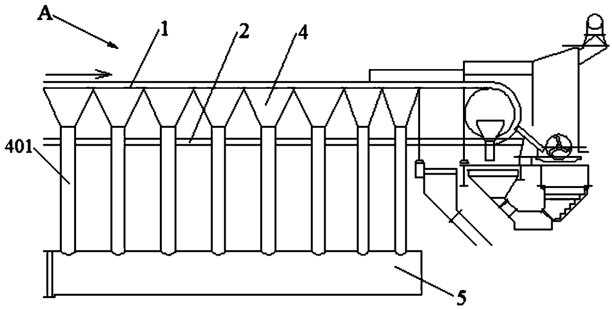
[0186] 1) Put the sintering mixture into the sintering machine trolley 1 to ignite and start sintering;
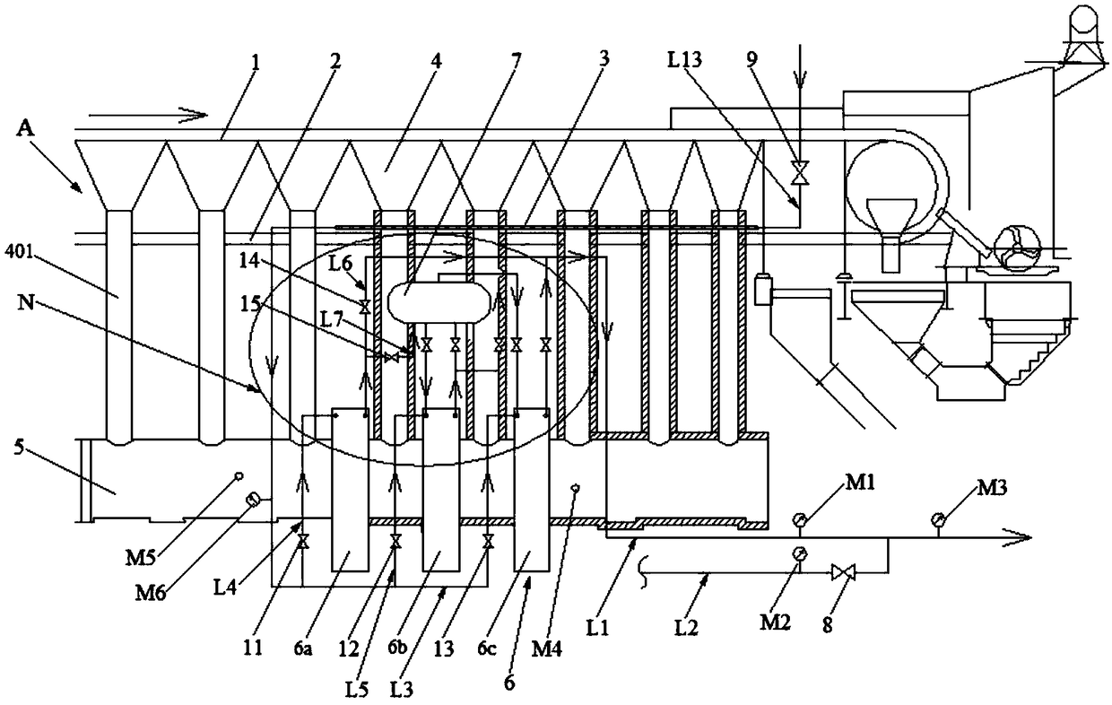
[0187] 2) A radiation heat exchanger 3 is installed above the return lane 2 at the rear of the sintering machine. The feed water enters the radiation heat exchanger 3 to exchange heat with the empty trolley 1 on the return lane 2, and the feed water is heated to become low-temperature water;
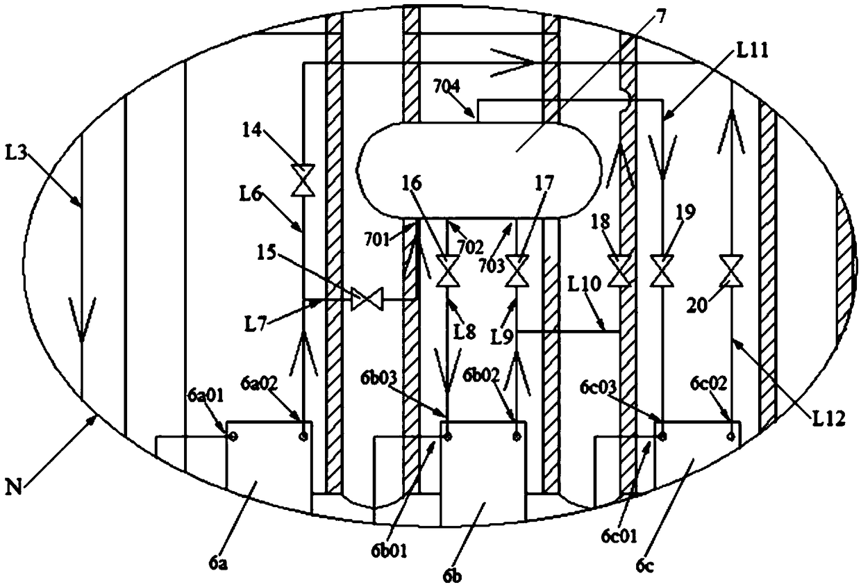
[0188] 3) Several wind boxes 4 at the tail of the sintering machine are equipped with a convection heat exchanger 6 at the position corresponding to the flue 5, and the low-temperature water enters the convection heat exchanger 6 to exchange heat with the high-temperature flue gas in the flue 5, and the low-temperature water passes through the high-temperature Steam is generated after the flue gas is heated;
[0189] ...
Embodiment 2
[0202] Repeat Example 1, except that in step 4), the steam is sent out through the steam main pipe L1 for use by the user. An external steam pipe L2 is also connected to the steam main pipe L1. The external steam is introduced through the external steam pipeline L2, and mixed with the steam in the steam main pipe L1 for use by users. The external steam pipe L2 introduces superheated steam.
[0203] In step 4), the first detection point M is set on the steam main pipe L1, the external steam pipeline L2 merges to the upstream of the steam main pipe L1 1 . Set the second detection point M on the external steam pipeline L2 2 . The third detection point M is set at the downstream of the external steam pipe L2 merging to the steam main pipe L1 3 . The first detection point M 1 On-line detection of steam flow Q at the corresponding position 1 and steam enthalpy h 1 . The second detection point M 2 On-line detection of steam flow Q at the corresponding position 2 and steam...
Embodiment 3
[0227] like figure 2 and 3 As shown, a multi-point recovery and high-efficiency utilization device for waste heat at the tail of a sintering machine, the device includes a sintering machine A, and a return lane 2 is provided under the tail of the sintering machine A. A plurality of bellows 4 are arranged under the trolley 1 of the sintering machine A. Each wind box 4 is connected to the lower flue 5 through its respective wind box branch pipe 401 . The device also includes a radiation heat exchanger 3 and a convective heat exchanger 6 . Wherein the radiation heat exchanger 3 is arranged above the return lane 2 . The convective heat exchanger 6 is arranged on the flue 5 corresponding to several wind boxes 4 at the tail of the sintering machine A. The water outlet 304 of the radiant heat exchanger 3 is connected to the inlet of the convective heat exchanger 6 .
[0228] The convective heat exchanger 6 is a three-stage multi-tube wear-resistant convective heat exchanger.
...
PUM
 Abstract
Description
Claims
Application Information
 - R&D
- Intellectual Property
- Life Sciences
- Materials
- Tech Scout
- Unparalleled Data Quality
- Higher Quality Content
- 60% Fewer Hallucinations
Browse by: Latest US Patents, China's latest patents, Technical Efficacy Thesaurus, Application Domain, Technology Topic, Popular Technical Reports.
© 2025 PatSnap. All rights reserved.Legal|Privacy policy|Modern Slavery Act Transparency Statement|Sitemap|About US| Contact US: help@patsnap.com