
Underwater stone throwing and grouting reinforcing method for hanging soft foundation at lower part of immersed tube

A soft foundation, immersed tube technology, applied in waterway systems, water supply devices, sewer pipeline systems, etc., can solve the problems of incomplete pumping, long construction period, complicated construction procedures, etc.

Active Publication Date: 2018-11-13
CHINA FIRST METALLURGICAL GROUP
View PDF8 Cites 4 Cited by
  • Summary
  • Abstract
  • Description
  • Claims
  • Application Information

AI Technical Summary

Problems solved by technology

However, some pipelines cannot be stopped due to production needs, and some pipelines are pressurized or siphon-type pipelines, which cannot be cut off and diverted at all.
[0003] Some design units will design a small box culvert or a small bridge to cross the above situation. Although it can solve the road design problem, it is undoubtedly necessary to add a box culvert or bridge project. The construction of the substructure also requires cofferdam method drainage, steel plate Enclosure and pile foundation bearing capacity, the construction process is complicated, the construction period is long, and because the river bank is a geological structure layer with strong permeability such as silt sand, it will cause the problem that the pumping cannot be completely done, and the entire project cost is very high

Method used


Image

  • Underwater stone throwing and grouting reinforcing method for hanging soft foundation at lower part of immersed tube
  • Underwater stone throwing and grouting reinforcing method for hanging soft foundation at lower part of immersed tube
  • Underwater stone throwing and grouting reinforcing method for hanging soft foundation at lower part of immersed tube

Examples


Embodiment Construction

[0041] In order to make the object, technical solution and advantages of the present invention more clear, the present invention will be further described in detail below in conjunction with the accompanying drawings and embodiments. It should be understood that the specific embodiments described here are only used to explain the present invention, not to limit the present invention.

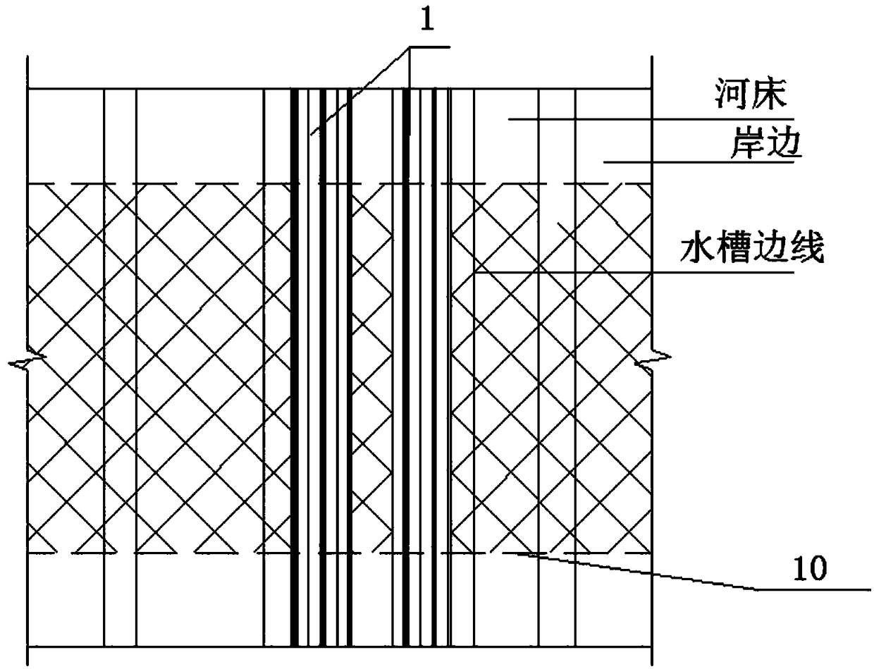
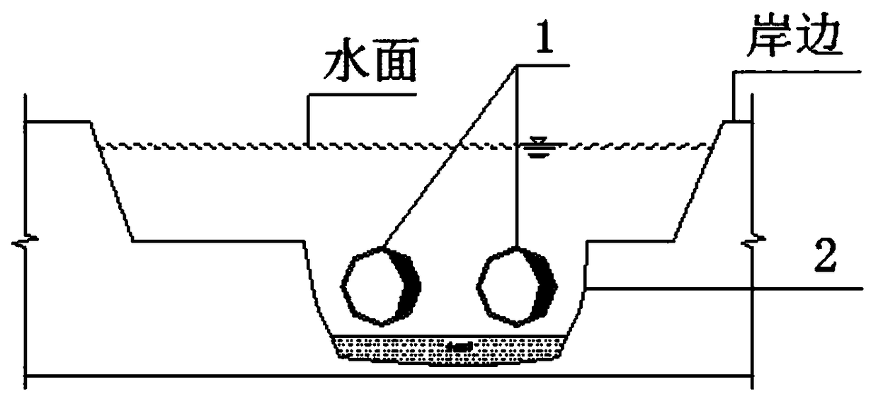
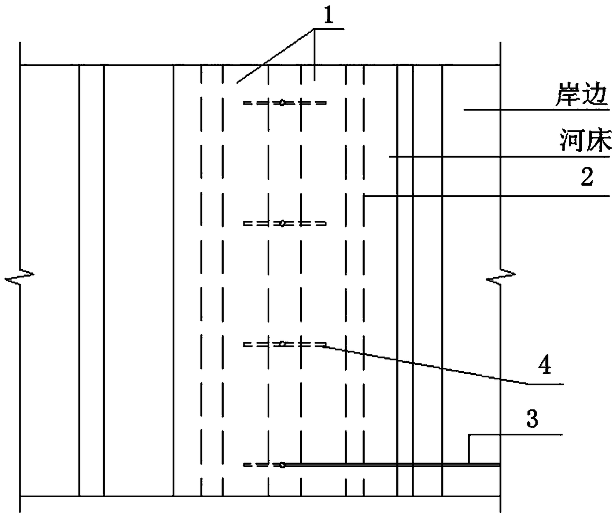
[0042] see Figure 1-Figure 6 , an underwater riprap grouting reinforcement method for a suspended soft foundation under an immersed tube, comprising the following steps:

[0043] 1) Within the red line of the road, according to the slope of the slope, release the sideline of the foot of the slope, use the geophysical method to detect the specific position of the pipeline 1 (immersed pipe) and determine the range of riprap, and make marks on the water surface to prevent riprap The pipeline was smashed during construction; the tank 2 with an inverted trapezoidal structure was excavated according...


PUM

PropertyMeasurementUnit
Particle sizeaaaaaaaaaa
Thicknessaaaaaaaaaa

Abstract

The invention discloses an underwater stone throwing and grouting reinforcing method for a hanging soft foundation at the lower part of an immersed tube. The method comprises the following steps: first, finding out the position of a pipeline, and excavating a water channel; throwing stone to the water channel, thus forming a stone-throwing silt squeezing layer; pre-burying a plurality of groutingpipelines at the position, close to the bottom, of the stone-throwing silt squeezing layer; then still throwing stone to the water channel, thus forming a stone-piled layer; then carrying out backfilling on the part around the pipeline by adopting stone chips till the water channel is level, thus forming a buffer layer; then covering the surface of the buffer layer with seepage-proofing geotechnical cloth, and carrying out backfilling on the seepage-proofing geotechnical cloth with gravel; then carrying out grouting and mud pumping simultaneously, thus forming a compact stone piled concrete structure; and finally, carrying out road pavement construction through layered paving and pressing according to the roadbed reequipments of road design. With the technical scheme, the purpose that whenthe waterway after construction adopting the immersed tube method encounters the construction road, the reinforcing for the foundation of the hanging part at the lower part of the immersed tube achieves the design bearing capacity requirements of the road is achieved, the method is simple and feasible, and the construction cost is low.

Description

technical field [0001] The invention belongs to the technical field of pipeline construction, and in particular relates to an underwater riprap grouting reinforcement method for a suspended soft foundation under an immersed pipe. Background technique [0002] In the construction of municipal road projects, it is often encountered that the ditch with the immersed pipe method is passed down. When the immersed pipe is placed, the cushion layer at the bottom of the tank is not smooth, causing the pipe to not sink evenly at the bottom of the underwater tank. Therefore, a thick layer of silt will be deposited between the cushion and the pipeline. When the road construction encounters ditches, the construction method of riprapping and silting is usually adopted, that is, the cofferdam is pumped first, and then the rubble is thrown and filled to squeeze the silt, and the layers are rolled and compacted. However, due to the support of the pier and the suspended pipeline in the middl...

Claims


Application Information

Patent Timeline
IPC IPC(8): E03F3/06
CPCE03F3/06
Inventor 湛学林张志海夏志聪陶卫军
Owner CHINA FIRST METALLURGICAL GROUP
Learn More