A device for blast furnace slag rotary granulation
A blast furnace slag and granulation technology, which is applied in the field of blast furnace slag utilization, can solve the problems of large particle size of granulated slag, low granulation efficiency, and reduced fluidity of slag film.
- Summary
- Abstract
- Description
- Claims
- Application Information
AI Technical Summary
Problems solved by technology
Method used
Image

Examples
Embodiment 1
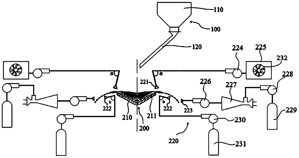
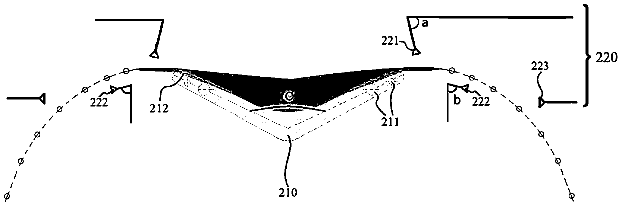
[0036] combine Figure 1~4 As shown, a blast furnace slag rotary granulation device in this embodiment includes a slag loading unit 100, a granulation unit 200 and a casing 500; the granulation unit 200 is arranged inside the casing 500, and the granulation unit 200 includes a rotary The disc 210 and the cooling mechanism 220, the rotating slag pan 210 is provided with a heating element 211, the slag nozzle 221, the liquefaction nozzle 222 and the atomizing nozzle 223 of the cooling mechanism 220 are arranged on the peripheral edge of the rotating slag pan 210; the above-mentioned slag loading unit 100 It includes a slag tank 110 and a slag discharge channel 120 , the slag discharge channel 120 is arranged at the bottom of the slag tank 110 , and the outlet of the slag discharge channel 120 is located above the rotating slag pan 210 .
[0037] The blast furnace slag transported from the blast furnace is stored in the slag pot 110, and flows into the rotating slag pan 210 throu...
Embodiment 2
[0042] The basic content of this embodiment is the same as that of Embodiment 1, the difference is that: the slag nozzle 221 is arranged above the edge of the rotating slag pan 210. In this embodiment, there are 16 slag nozzles 221, and the slag nozzle 221 rotates along the The circumference above the edge of the slag pan 210 is uniformly distributed. In this embodiment, the slag nozzle 221 uses gas as a carrier to spray granulated slag with a smaller particle size to the edge of the rotating slag pan 210. The carrier for spraying granulated slag can also be other fluids such as water. The granulated slag with a small particle size is sprayed, so that the granulated slag with a certain kinetic energy and the blast furnace slag at the edge of the rotating slag pan 210 collide and fuse to grow up, so that the granulated slag that did not meet the resource utilization conditions before can be secondary produced Utilization; on the other hand, the slag film is broken through the i...
Embodiment 3
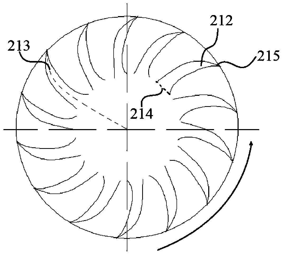
[0050] combine Figure 5 As shown, the basic content of this embodiment is the same as that of Embodiment 1, the difference is that a raised surface 216 is provided between two adjacent slag troughs 212, and stoppers are provided at both ends of the circumferential edge of the raised surface 216. plate 217, so that the baffle plate 217 is located on both sides of the slag outlet of the slag flow tank 212, and the slag outlet of the slag flow tank 212 is the circumferential side 215. Its function is: the blast furnace slag located on the rotating slag pan 210 moves towards the edge of the rotating slag pan 210 under the action of centrifugal force, and part of the blast furnace slag flows out along the slag flow groove 212 through the slag outlet; On the convex surface 216, and then flow to the peripheral edge of the convex surface 216, when this part of the blast furnace slag moves to the peripheral edge position of the convex surface 216, it will be blocked by the baffle plat...
PUM
 Abstract
Description
Claims
Application Information
 - R&D
- Intellectual Property
- Life Sciences
- Materials
- Tech Scout
- Unparalleled Data Quality
- Higher Quality Content
- 60% Fewer Hallucinations
Browse by: Latest US Patents, China's latest patents, Technical Efficacy Thesaurus, Application Domain, Technology Topic, Popular Technical Reports.
© 2025 PatSnap. All rights reserved.Legal|Privacy policy|Modern Slavery Act Transparency Statement|Sitemap|About US| Contact US: help@patsnap.com