A kind of corrugated paper manufacturing equipment

A technology for manufacturing equipment and corrugated paper, which is applied in the field of corrugated paper manufacturing equipment and can solve the problem that core paper cannot stick

Active Publication Date: 2020-10-20
淮北鸣朋环保科技有限公司
View PDF6 Cites 0 Cited by
  • Summary
  • Abstract
  • Description
  • Claims
  • Application Information

AI Technical Summary

Problems solved by technology

[0007] Aiming at the problems in the prior art, the present invention provides a corrugated paper manufacturing equipment, which transports the core paper that needs to be bonded by including the first conveying mechanism and the second conveying mechanism, and the core wheel realizes the alignment of the core paper The paint is applied and stuck by the paint assembly mechanism, the first pressing mechanism and the second pressing mechanism press the stuck core paper, and the edge trimming mechanism realizes cutting the side ; The container is provided with a special structure, when the paint inside is in use, the remaining amount of the paint can be accurately observed through the observation window, and can be added in time to avoid the decline of the paint from causing the core paper Can not be glued, and at the same time does not affect the whole processing process, convenient and convenient; After the core paper is glued, use the rotating conveyor belt to press with heating to promote the rapid solidification of the glue, and at the same time the protrusions are pressed together, Ensure that each position of the core paper fits more tightly; after the bonding is completed, the cutting blade can be rotated to make contact with the core paper, and the sponge pad is used to press both sides of the cutting blade to make the rotating cutting blade Quickly cut the parts on both sides according to the needs, and the pressing method can keep the cutting edge neat

Method used


Image

  • A kind of corrugated paper manufacturing equipment
  • A kind of corrugated paper manufacturing equipment
  • A kind of corrugated paper manufacturing equipment

Examples


Embodiment Construction

[0029] In order to make the technical means, creative features, goals and effects achieved by the present invention easy to understand, the present invention will be further described below in conjunction with specific embodiments.

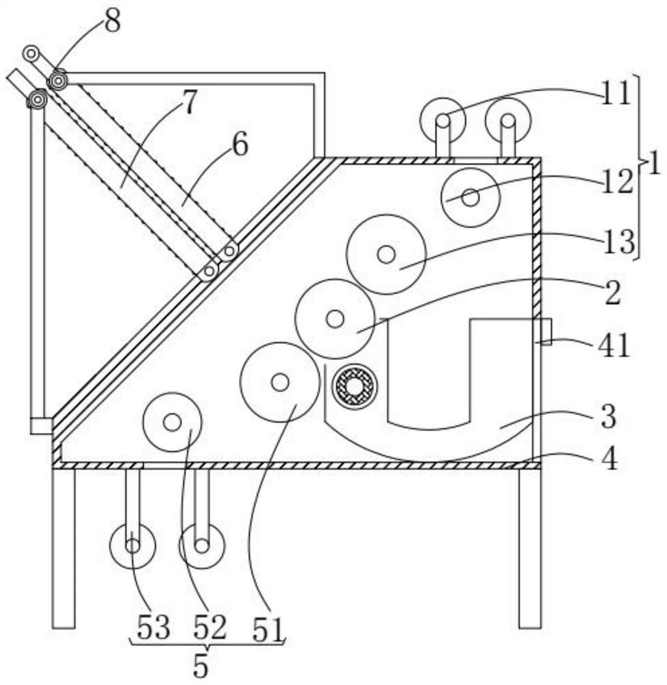
[0030] Such as figure 1 As shown, a kind of corrugated paper manufacturing equipment according to the present invention includes a first conveying mechanism 1, a core wheel 2, a coating assembly mechanism 3, a casing 4, a second conveying mechanism 5, a first pressing mechanism 6, a second pressing mechanism The moving mechanism 7 and the trimming mechanism 8, the top of the shell 4 is provided with the first conveying mechanism 1 for conveying a core paper, and the bottom of the shell 4 is provided with the second conveying mechanism for another core paper conveying. Conveying mechanism 5; The core wheel 2 that presses and bonds two core papers is provided between the second conveying mechanism 5 and the first conveying mechanism 1; the bottom en...


PUM


Abstract

The invention relates to the field of corrugated paper making and in particular relates to corrugated paper making equipment which comprises a first conveying mechanism, a core wheel, a coating collection mechanism, a shell, a second conveying mechanism, a first pressing moving mechanism, a second pressing moving mechanism and an edge cutting mechanism, wherein core paper to be bonded is conveyedthrough the first conveying mechanism and the second conveying mechanism; coating and bonding are carried out on the core paper by using the core wheel through the coating collection mechanism; the first pressing moving mechanism and the second pressing moving mechanism are adopted for pressing the bonded core paper; the edge cutting mechanism is used for cutting side edges. Due to a special structure of a containing box of the equipment, when a coating inside is used, the residual amount of the coating can be accurately observed through an observation window; after being bonded, the core paper is pressed through a rotating conveying belt under heating, then rapid curing of an adhesive can be promoted, both sides of a cutting blade are pressed through sponge pads, and then excessive partson both sides can be rapidly cut by using the rotating cutting blade according to demands.

Description

technical field [0001] The invention relates to the field of corrugated paper manufacturing, in particular to corrugated paper manufacturing equipment. Background technique [0002] Corrugated paper is a plate made of liner paper and corrugated corrugated paper formed by processing corrugated sticks. It is generally divided into two types: single corrugated board and double corrugated board. Corrugated paper has low cost, light weight, easy processing, and high strength. Large size, excellent printing adaptability, convenient storage and transportation, etc. More than 80% of corrugated paper can be recycled. Corrugated paper can be used as packaging for food or digital products. It is relatively environmentally friendly and widely used. [0003] The bonding of core paper is an important step in the manufacture of corrugated paper. When the existing core paper is glued, because the glue is inside the shell, when the glue drops to the bottom of the coating wheel, it cannot be ...

Claims


Application Information

Patent Timeline
Patent Type & Authority Patents(China)
IPC IPC(8): B32B37/00B32B37/12B32B38/04
CPCB32B37/0053B32B37/1284B32B38/04B32B2038/045
Inventor 崔雪柯吴昊
Owner 淮北鸣朋环保科技有限公司
Why Eureka
Try Eureka