A pressure control device and a pressure increase and decrease control method

A technology of pressure control and control method, which is applied in the direction of fluid pressure actuators, fluid pressure converters, fluid pressure actuator system components, etc., and can solve the difficulty of ensuring control accuracy and work stability, and the difficulty of precise control of hydraulic systems Increase the problem of unfavorable power supply and oil supply, achieve the effect of high adjustment accuracy and stability, reduce structural cost and energy consumption, and improve accuracy and stability

Active Publication Date: 2020-08-21
CHINA NAT OFFSHORE OIL CORP +2
View PDF5 Cites 0 Cited by
  • Summary
  • Abstract
  • Description
  • Claims
  • Application Information

AI Technical Summary

Problems solved by technology

[0003] However, in the underground high temperature and high pressure environment, due to the decrease of fluid viscosity under high temperature and high pressure, and the influence of harsh working conditions, it is more difficult for the hydraulic system to achieve precise control through simple methods. The conventional high precision pressure control system is applied in the For downhole equipment, it is often limited by factors such as small installation space in the downhole, unfavorable power supply and oil supply, and inconvenient on-site operation, which makes it difficult to guarantee the control accuracy and working stability of the pressure control device of the hydraulic system.
Therefore, it is still a difficult problem in the industry to overcome the complexity of the pressure control of the downhole hydraulic system and develop a hydraulic system pressure control device with high regulation efficiency, high control accuracy, strong applicability and high stability.

Method used


Image

  • A pressure control device and a pressure increase and decrease control method
  • A pressure control device and a pressure increase and decrease control method

Examples


Embodiment Construction

[0046] In order to make the purpose, technical solution and advantages of the present invention more clear, the embodiments of the present invention will be described in detail below in conjunction with the accompanying drawings. It should be noted that, in the case of no conflict, the embodiments in the present application and the features in the embodiments can be combined arbitrarily with each other.

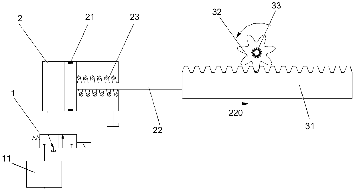
[0047] This embodiment provides a pressure control device, including a power assembly, a transmission assembly and a pressure regulating valve 6 connected in sequence, the transmission assembly includes a two-way clutch, and the two-way clutch has a first transmission state and a second transmission state; the When the two-way clutch is in the first transmission state, when the power assembly moves in the first direction 220, the two-way clutch is engaged to drive the pressure regulating valve 6 to perform pressurization action, and the power assembly moves along the first dir...


PUM


Abstract

The invention provides a pressure control device and a pressure increasing and decreasing control method. The pressure control device comprises a power assembly, a transmission assembly and a pressureregulating valve connected in sequence, wherein under the condition that a bidirectional clutch in the transmission assembly is in a first transmission state, when the power assembly moves in the first direction, the bidirectional clutch is engaged to drive the pressure regulating valve to carry out pressurization action, and when the power assembly is reversely reset in the second direction, thebidirectional clutch is separated; under the condition that the bidirectional clutch is in a second transmission state, when the power assembly moves in the second direction, the bidirectional clutchis engaged to drive the pressure regulating valve to perform pressure reduction action, and when the power assembly is reversely reset in the first direction, the bidirectional clutch is separated. By the adoption of the bidirectional clutch, the process of increasing and reducing the pressure of a hydraulic system is realized, the structural assemblies are simplified, and the equipment utilization rate is high; and the pressure control device has the advantages that pressure regulating operation is simple and convenient, occupied mounting space is small, the structural cost is low and energyconsumption is low.

Description

technical field [0001] The invention relates to the field of pressure control equipment, and more specifically, to a pressure control device and a method for controlling cycle increase and decrease. Background technique [0002] For formation testing instruments, most of them use the hydraulic system to drive the executive components to complete the operation processes such as seat seal, sampling, coring, and pressure measurement. Precise control of pressure is critical to instrument reliability and timeliness. [0003] However, in the underground high temperature and high pressure environment, due to the decrease of fluid viscosity under high temperature and high pressure, and the influence of harsh working conditions, it is more difficult for the hydraulic system to achieve precise control through simple methods. The conventional high precision pressure control system is applied in the For downhole equipment, it is often limited by factors such as small installation space...

Claims


Application Information

Patent Timeline
Patent Type & Authority Patents(China)
IPC IPC(8): F15B3/00F15B21/08F15B13/02
CPCF15B3/00F15B13/02F15B21/08
Inventor 陈永超冯永仁周明高李碧柳张平王林根薛永增杜小强刘康
Owner CHINA NAT OFFSHORE OIL CORP
Why Eureka
Try Eureka