
A miniaturized three-band unidirectional radiating antenna

A radiating antenna, one-way technology, applied in the direction of antenna, resonant antenna, antenna components, etc., to achieve the effect of increasing electrical height, large span, and compact electrical size

Active Publication Date: 2020-09-29
SOUTHEAST UNIV +1
View PDF5 Cites 0 Cited by
  • Summary
  • Abstract
  • Description
  • Claims
  • Application Information

AI Technical Summary

Problems solved by technology

Although directional multi-band antennas and directional broadband / ultra-wideband antennas have been extensively studied, there is currently no antenna that can cover the above-mentioned multiple frequency bands including an ultra-wideband, while having a compact electrical size and unidirectional radiation characteristics

Method used


Image

  • A miniaturized three-band unidirectional radiating antenna
  • A miniaturized three-band unidirectional radiating antenna
  • A miniaturized three-band unidirectional radiating antenna

Examples


Embodiment Construction

[0040] The present invention will be further described below in conjunction with the accompanying drawings.

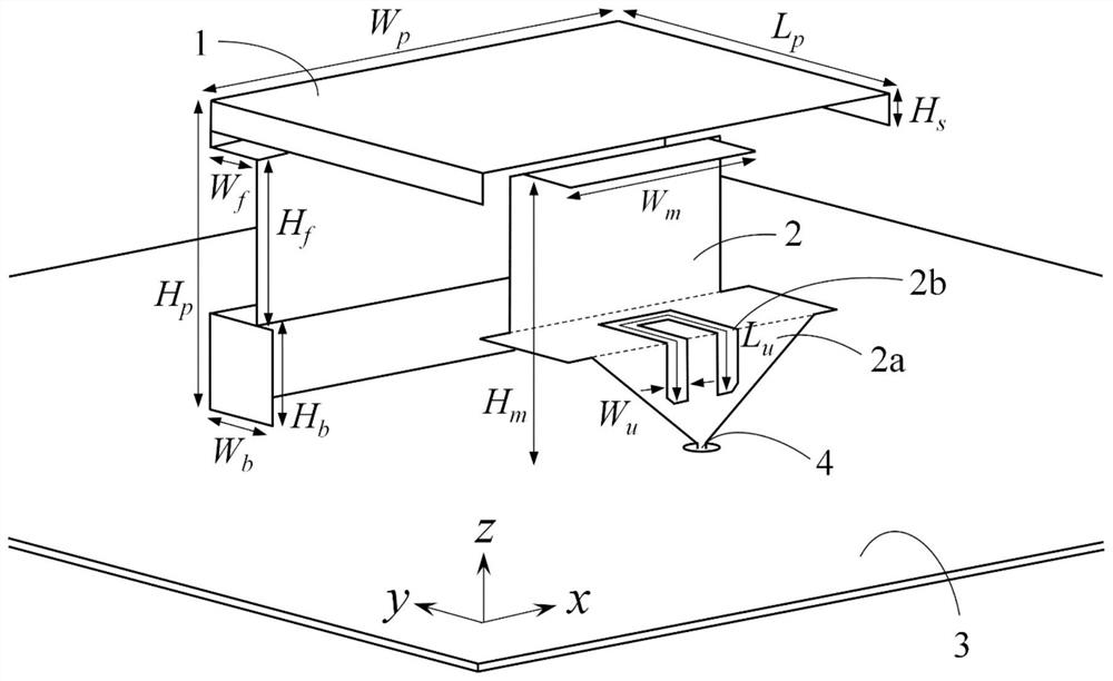
[0041] A miniaturized three-band unidirectional radiation antenna of the present invention comprises a quasi-L-shaped metal plate 1 and a metal bending monopole 2 . The bottom of the quasi-L-shaped metal plate 1 is electrically connected to the metal floor 3 , and the bent metal monopole 2 is located under the quasi-L-shaped metal plate 1 and vertically arranged on the metal floor 3 . The antenna adopts the traditional coaxial waveguide feeding method, the characteristic impedance is 50 ohms, and the metal bending monopole 2 is fed from the bottom of the metal floor 3, and the inner conductor of the coaxial waveguide feeding line 4 is connected to the bottom of the metal bending monopole 2 connected.

[0042] In the design, the length L of the quasi-L-shaped metal plate 1 p and height H p Determines the minimum operating frequency of the antenna. At this time, the w...


PUM


Abstract

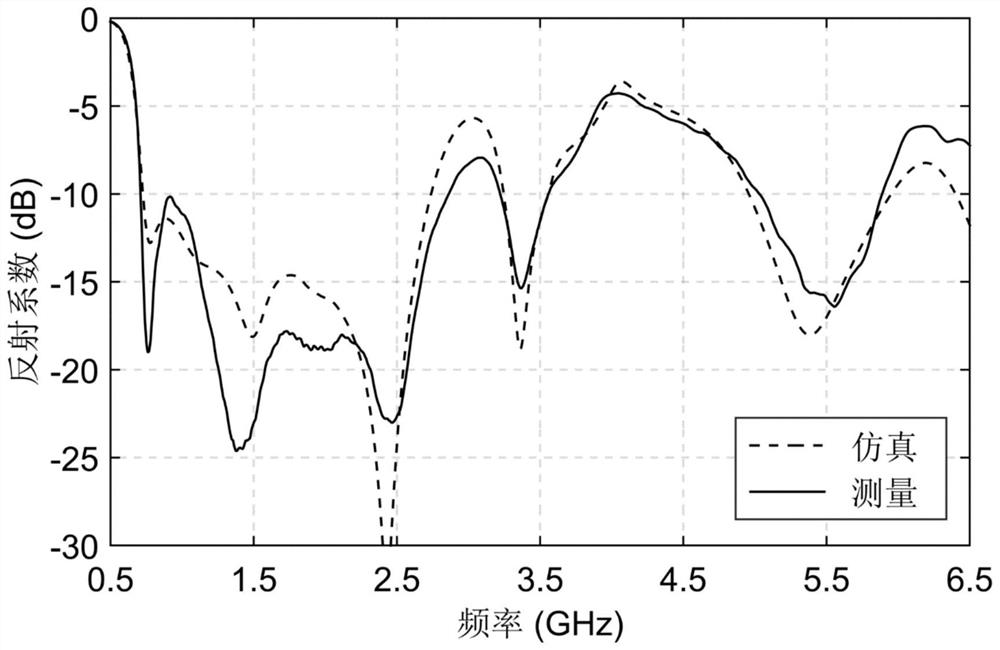
Disclosed is a miniaturized three-frequency-band unidirectional radiation antenna. The bottom of a quasi-L-shaped metal plate (1) of the antenna is connected to a metal floor (3). Two sides of a horizontal part of the quasi-L-shaped metal plate (1) are bent inwards, the middle part of a vertical part thereof is recessed inwards, and two sides of the lower part of the vertical part are bent inwards. A bent metal monopole (2) is located below the quasi-L-shaped metal plate (1) and is vertically arranged on the metal floor (3), the lower part of the bent metal monopole (2) is a triangular impedance-matching part (2a), and a three-dimensional U-shaped groove (2b) is engraved on the bent metal monopole (2). A coaxial waveguide feed line (4) is located at a circular hole in the bottom of the metal floor (3), and an inner conductor of the coaxial waveguide feed line (4) is connected to the bottom of the bent metal monopole (2). By using the structure of the present invention, a miniaturized three-frequency-band unidirectional radiation antenna with high radiation efficiency can be realized, and the lowest operating frequency band is an ultra-wide frequency band with a relative bandwidth of up to 4: 1.

Description

technical field [0001] The invention belongs to the field of wireless communication system electronic devices, in particular to a miniaturized three-band unidirectional radiation antenna, which supports almost all wireless communication services below 6 GHz, and is suitable for airport high-speed communication, broadband multi-mode software radio communication, and fifth-generation mobile communication , vehicle communication and other fields. Background technique [0002] With the maturity of civil aviation technology and the popularization of aviation service industry, more and more people will take air as the first choice for medium and long-distance travel. For the safety of aircraft flight, between the time the aircraft lands at the airport and the next take-off, the airport control center and the aircraft need to interact with a large amount of data, including the technical data recorded by the aircraft during the flight, and the airlines that need to transmit the data...

Claims


Application Information

Patent Timeline
Patent Type & Authority Patents(China)
IPC IPC(8): H01Q1/28H01Q1/36H01Q1/48H01Q1/50H01Q5/10H01Q5/28H01Q9/42H01Q15/18H01Q19/10
CPCH01Q1/285H01Q1/36H01Q1/48H01Q1/50H01Q5/10H01Q5/28H01Q9/42H01Q15/18H01Q19/106
Inventor 蒋之浩洪伟余超张雷张彦蔡龙珠郑司斗
Owner SOUTHEAST UNIV
Learn More