
Microwave converter

A converter and microwave technology, applied in the field of microwave converters, can solve the problems of insufficient number of microwaves, failure to remove algae and sterilization, and ultraviolet wavelengths not within the standard range, and achieve reasonable design, simple structure, and good algae removal and sterilization. The effect of disinfection

Pending Publication Date: 2018-11-06
青岛浩润水环境科技有限公司
View PDF0 Cites 0 Cited by
  • Summary
  • Abstract
  • Description
  • Claims
  • Application Information

AI Technical Summary

Problems solved by technology

The microwave converters in the current algae removal, sterilization and disinfection processing equipment generally have the defect that the number of microwaves entering the resonant cavity is insufficient, and the electrodeless lamp cannot be effectively activated or the power of the activated electrodeless lamp is insufficient, resulting in the ultraviolet rays emitted. The wavelength is not within the standard range, and the effect of algae sterilization and disinfection cannot be achieved

Method used


Image

  • Microwave converter
  • Microwave converter
  • Microwave converter

Examples


Embodiment 1

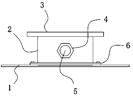
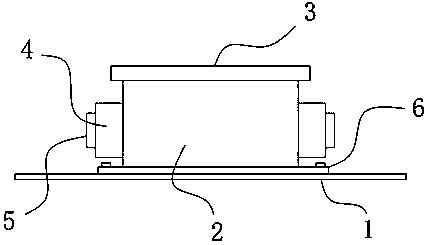
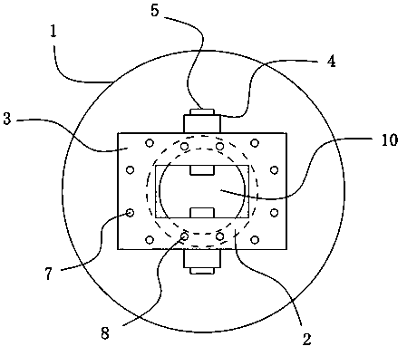
[0023] see Figure 1-4 , a microwave converter, including a mounting plate 1, a waveguide 2 is fixedly installed on the mounting plate 1, and two symmetrically arranged adjusting bolts 5 are threaded on the side walls of the waveguide 2, and the adjusting bolts 5 are The end away from the waveguide 2 is sleeved with a nut 4, the upper end of the waveguide 2 is fixedly installed with a connecting plate 3, the upper end of the waveguide 2 is provided with several threaded holes, and the connecting plate 3 is provided with several mounting holes 7 and connected with The threaded hole is vertically corresponding to the connecting hole 8; the connecting plate 3 is provided with a microwave inlet hole 10 vertically corresponding to the inside of the waveguide 2, and the bottom of the mounting plate 1 is provided with a microwave outlet hole vertically corresponding to the inside of the waveguide 2 9.

[0024] The usage method and working principle of this embodiment:

[0025] When...

Embodiment 2

[0029] On the basis of Embodiment 1, in addition, the microwave exit hole 9 is a rectangular hole structure, and the lengths of its long side and short side are 87mm and 43mm respectively; the microwave exit hole 9 is a circular hole structure, and its diameter is 74mm. The connecting plate 3 is a rectangular plate structure, the length and width of the connecting plate 3 are 138mm and 95mm respectively, the mounting plate 1 is a circular plate structure, the diameter of the mounting plate 1 is 231mm, and the diameter of the adjusting bolt 5 is 9.7mm.


PUM


Abstract

The invention discloses a microwave converter, and relates to the technical field of environment protection equipment. The microwave converter comprises an installation disc and a waveguide tube fixedly installed on the installation disc, wherein two symmetrically arranged adjustment bolts are in threaded connection with the side wall of the waveguide tube and penetrate the same; nuts are connected with one end, far away from the waveguide tube, of the adjustment bolts in a sleeving manner; a connection plate is fixedly installed at the upper end of the waveguide tube; a microwave inlet perpendicularly corresponding to the interior of the waveguide tube is formed in the connection plate; and a microwave outlet perpendicularly corresponding to the interior of the waveguide tube is formed inthe bottom of the installation disc. The microwave converter provided by the invention is simple in structure; the microwave converter is made from aluminum alloy, so as not to have magnetic conductivity; parameters of the device such as the sizes of the microwave outlet and the microwave inlet play a decisive role in the quantity of microwaves entering a resonant cavity, the condition that the enough microwaves enter the resonant cavity is ensured, the normal working power for activating the electrodeless lamp is ensured, and thus the wave length of ultraviolet rays emitted by the lamp is within a standard range, and the good effects of removing algae, sterilizing and disinfecting are achieved.

Description

technical field [0001] The invention relates to the technical field of environmental protection equipment, in particular to a microwave converter. Background technique [0002] With the continuous development of society, people's awareness of environmental protection is also constantly increasing, and the water quality requirements for various types of water are also getting higher and higher. At present, the main sterilization methods include liquid chlorine, nitrogen dioxide disinfection, ozone disinfection, etc. Traditional sterilization and disinfection methods have many disadvantages, such as residual chlorine disinfection, poor safety, and high cost of ozone disinfection. At present, the treatment equipment that uses ultraviolet rays to sterilize drinking water, recycled water, beverages, alcohol, swimming pools, etc., has the characteristics of broad-spectrum sterilization and disinfection, safety and no secondary pollution, and ultraviolet rays are emitted through el...

Claims


Application Information

Patent Timeline
Patent Type & Authority Applications(China)
IPC IPC(8): H01P5/103H01J65/04
CPCH01P5/103H01J65/044
Inventor 王庆凯
Owner 青岛浩润水环境科技有限公司
Learn More