Method for adjusting self-collimation of interference optical path in holographic grating lithography system

A technology of holographic grating and lithography system is applied in the field of adjustment of the self-collimation optical path of the interference optical path, which can solve the problems of poor parallelism of the exposure beam and the like.

Active Publication Date: 2018-11-06
SUZHOU UNIV
View PDF14 Cites 8 Cited by
  • Summary
  • Abstract
  • Description
  • Claims
  • Application Information

AI Technical Summary

Problems solved by technology

[0003] In order to solve the technical problem of poor parallelism of exposure light beams when making parallel and equally spaced striped holographic gratings, the technical solution of the present invention is as follows:

Method used


Image

  • Method for adjusting self-collimation of interference optical path in holographic grating lithography system
  • Method for adjusting self-collimation of interference optical path in holographic grating lithography system
  • Method for adjusting self-collimation of interference optical path in holographic grating lithography system

Examples


Embodiment 1

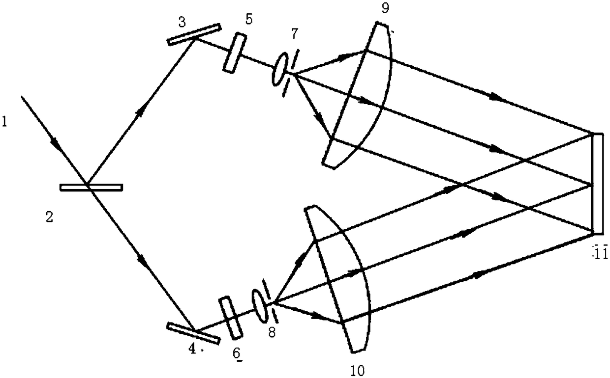
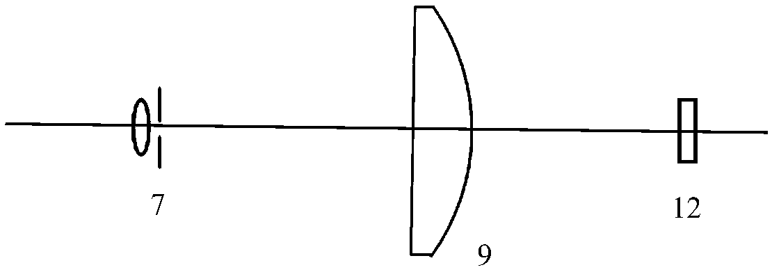
[0024] A method for adjusting the self-collimation of interference optical paths in a holographic grating photolithography system, the holographic grating photolithography system is used to make holographic gratings with parallel and equidistant stripes; the holographic grating photolithography system is as follows figure 1 Shown: including coherent light source 1, beam splitter 2, first mirror 3, second mirror 4, first aperture 5, second aperture 6, first pinhole filter 7, second pinhole filter device 8, the first collimating lens 9, the second collimating lens 10, the holographic recording dry plate 11 to be exposed, the plane mirror 12, the first volume Bragg grating 13, the first photodetector 14; the above-mentioned optical elements They are all placed on the holographic platform; the light emitted by the coherent light source is divided into the transmitted light path and the reflected light path after passing through the beam splitter; the first mirror, the first pinhol...

Embodiment 2

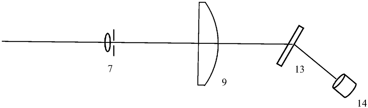
[0036] A photolithographic system for fabricating parallel and equally spaced striped holographic gratings, such as Figure 4 As shown: the holographic grating photolithography system is used to make a holographic grating with parallel and equally spaced stripes; the holographic grating photolithography system includes a coherent light source 1, a beam splitter 2, a first mirror 3, a second mirror 4, The first aperture 5, the second aperture 6, the first pinhole filter 7, the second pinhole filter 8, the first collimating lens 9, the second collimating lens 10; the first volume Bragg grating 13, the second Two-body Bragg grating 16, first photodetector 14, second photodetector 15;

[0037] The light emitted by the coherent light source is divided into the transmitted light path and the reflected light path after passing through the beam splitter; the first mirror, the first diaphragm, the first pinhole filter, and the first collimating lens are placed in sequence on the reflec...


PUM


Abstract

The invention belongs to the field of information optics and relates to a method for adjusting the self-collimation of an interference optical path in a holographic grating lithography system to solvethe poor parallelism of exposure beams when a parallel equidistant stripe holographic grating is fabricated. A volume Bragg grating is placed behind a collimating lens. The incident angle of the exposure beam emitted to the volume Bragg grating is equal to the Bragg angle of the volume Bragg grating. A photoelectric detector is placed on an -1 grade transmission diffraction optical path after theexposure beam is emitted to the volume Bragg grating. A pinhole filter is moved forwards and backwards along an optical axis to observe the readings of the photoelectric detector in real time. When the photoelectric detector has a maximum reading, the pinhole filter is fixed and the distance between a first pinhole filter and a first collimating lens is kept constant. The method for adjusting theself-collimating optical path detects the parallelism of self-collimated light by using the volume Bragg grating, substitutes for a traditional Moire fringe adjustment method, is easy to operate andhas a good practical value.

Description

technical field [0001] The invention belongs to the field of information optics, and relates to a method for adjusting an interference optical path and a self-collimating optical path. Background technique [0002] Plane-parallel equidistant stripe holographic grating is an important diffractive optical element, widely used in spectrometer, optical communication, optical metrology, strong laser system, etc. This type of grating also puts forward strict requirements on the parallelism of the grating stripes, and the poor parallelism of the recording light directly affects the wave aberration of the grating. Therefore, the self-collimation of the parallel light for recording the holographic grating is better. The optical device of the collimating optical path generally uses an aspheric lens or an off-axis parabolic mirror to self-collimate to obtain parallel light. The common detection methods for the collimation of holographic optical path include Moire fringe method and st...

Claims


Application Information

Patent Timeline
Patent Type & Authority Applications(China)
IPC IPC(8): G02B5/18G02B5/32G03F7/20
CPCG02B5/1857G02B5/32G03F7/70408
Inventor 邹文龙李朝明吴建宏陈新荣蔡志坚刘全
Owner SUZHOU UNIV
Why Eureka
Try Eureka