Heat pump system with heating and defrosting functions

A heat pump system and function technology, which is applied in the direction of compressor with reversible cycle, lighting and heating equipment, damage protection, etc., can solve the problems of long defrosting time, increased system compression ratio, incomplete defrosting, etc. Incomplete defrosting, avoid compression ratio increase, avoid the effect of long defrosting time

Pending Publication Date: 2018-11-06
GUANGDONG NEW ENERGY TECH DEV
View PDF6 Cites 4 Cited by
  • Summary
  • Abstract
  • Description
  • Claims
  • Application Information

AI Technical Summary

Problems solved by technology

[0002] According to market research, the heat pump system will frost when it operates in a low-temperature and high-humidity environment. Taking the air-conditioning system as an example, frost will form on the surface of the outdoor heat exchanger during winter operation. The surface of the outdoor heat exchanger is defrosted. During the defrosting process, the temperature of the throttled refrigerant is very low, which is quite different from the indoor temperature. When it enters the indoor heat exchanger, fogging will occur. The evaporation temperature is low, and in order not to make the indoor temperature too low, the fan of the indoor heat exchanger does not start during defrosting, so the indoor heat exchanger cannot fully evaporate and absorb heat, and the outdoor heat exchanger does not have enough residual heat for defrosting. The defrosting time is long and the defrosting is not complete. Moreover, the system operates at ultra-low temperature due to the low evaporation temperature, which will cause the system compression ratio to increase, which directly affects the reliability of the unit operation and increases the failure rate and repair rate of the unit.

Method used


Image

  • Heat pump system with heating and defrosting functions
  • Heat pump system with heating and defrosting functions

Examples


Embodiment Construction

[0018] In order to make the object, technical solution and advantages of the present invention clearer, the present invention will be further described in detail below by taking an air-conditioning system as an example, with reference to the accompanying drawings and embodiments. It should be understood that the specific embodiments described here are only used to explain the present invention, not to limit the present invention.

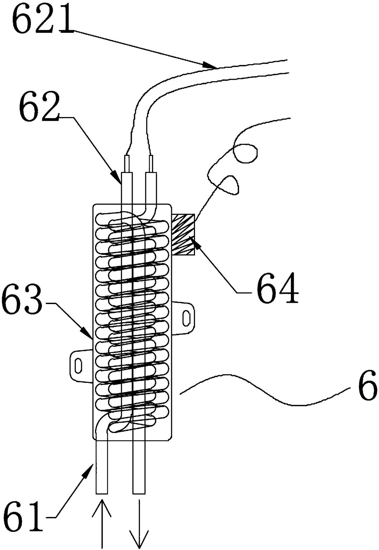
[0019] Such as figure 1 As shown, a heat pump system with heating and defrosting functions includes a compressor 1, a four-way valve 2, an outdoor heat exchanger 3 (equivalent to the first heat exchanger), and a throttling device 4 connected through a refrigerant circulation pipeline. And the indoor heat exchanger 5 (equivalent to the second heat exchanger), also includes a working fluid heater 6 for heating the refrigerant, and the working fluid heater 6 is connected in series between the outlet of the throttling device 4 and the inlet of the indoo...


PUM


Abstract

The invention belongs to the technical field of heat pumps, and particularly relates to a heat pump system with heating and defrosting functions. The heat pump system comprises a compressor, a four-way valve, a first heat exchanger, a throttling device and a second heat exchanger which communicate with one another through a refrigerant circulation pipeline. The heat pump system is characterized byfurther comprising a working medium heater used for heating a refrigerant; and the working medium heater is connected in series between the throttling device and the first heat exchanger or the second heat exchanger. The heat pump system provided by the invention has the beneficial effects that the working medium heater is connected in series between the throttling device and one indoor heat exchanger, so that the throttled low-temperature refrigerant can be heated, the temperature of the heated refrigerant can approach the indoor environment temperature, and the indoor heat exchange can be protected against the fogging phenomenon caused by excessive temperature differentials; and furthermore, the problems that the defrosting time is hugely long, the defrosting process is not thorough, aswell as the unit failure rate and repair rate are high can be solved.

Description

technical field [0001] The invention belongs to the technical field of heat pumps, in particular to a heat pump system with heating and defrosting functions. Background technique [0002] According to market research, the heat pump system will frost when it operates in a low-temperature and high-humidity environment. Taking the air-conditioning system as an example, frost will form on the surface of the outdoor heat exchanger during winter operation. The surface of the outdoor heat exchanger is defrosted. During the defrosting process, the temperature of the throttled refrigerant is very low, which is quite different from the indoor temperature. When it enters the indoor heat exchanger, fogging will occur. The evaporation temperature is low, and in order not to make the indoor temperature too low, the fan of the indoor heat exchanger does not start during defrosting, so the indoor heat exchanger cannot fully evaporate and absorb heat, and the outdoor heat exchanger does not ...

Claims


Application Information

Patent Timeline
Patent Type & Authority Applications(China)
IPC IPC(8): F25B13/00F25B47/02
CPCF25B13/00F25B47/02
Inventor 赵密升李建国陈国富郭飞祥
Owner GUANGDONG NEW ENERGY TECH DEV
Why Eureka
Try Eureka