
Simple clamping mechanism special for steel pipe

A technology of clamping mechanism and steel pipe, applied in the direction of clamping device, clamping, metal processing machine parts, etc., can solve the problems of steel pipe connection error, steel pipe position offset, etc., to reduce offset, reduce error, and improve firmness and stability effects

Pending Publication Date: 2018-11-06
WUXI SAFETY SCAFFOLDING
View PDF0 Cites 0 Cited by
  • Summary
  • Abstract
  • Description
  • Claims
  • Application Information

AI Technical Summary

Problems solved by technology

During welding, the operator generally places the steel pipe on a horizontal surface or directly fixes it by hand to complete the welding work of the steel pipe, but it is difficult to completely fix the steel pipe in this way, and the position of the steel pipe is likely to shift during the welding process, resulting in errors in the connection of the steel pipe

Method used


Image

  • Simple clamping mechanism special for steel pipe
  • Simple clamping mechanism special for steel pipe
  • Simple clamping mechanism special for steel pipe

Examples


Embodiment 1

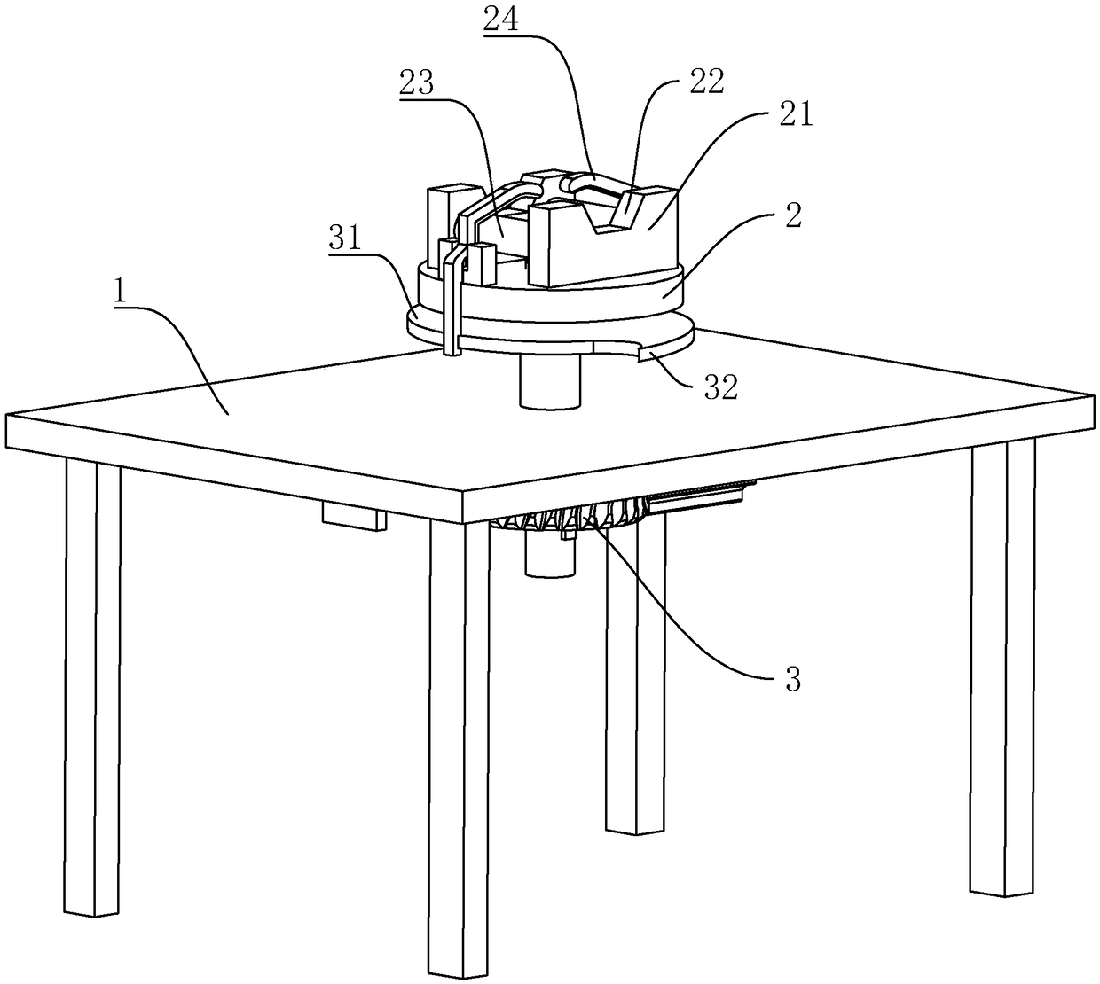
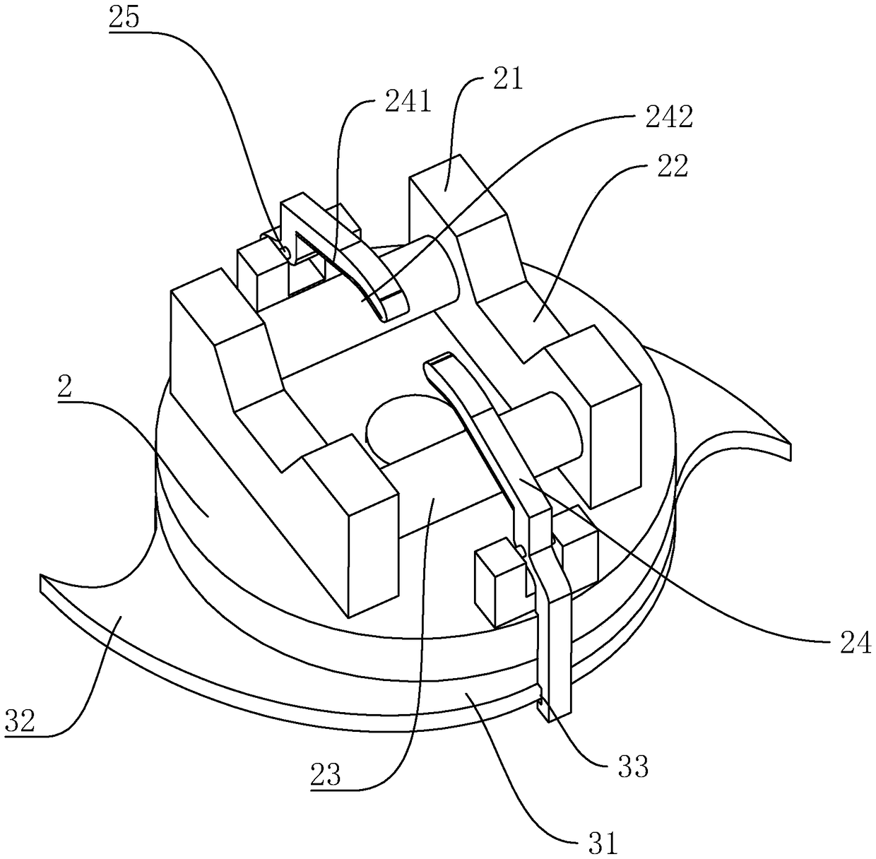
[0031] Embodiment 1, a kind of easy and simple steel pipe special-purpose clamping mechanism, such as figure 1 , figure 2 and image 3 As shown, it includes a rectangular frame 1 as a whole. The center position of the frame 1 is fixedly connected with a fixed plate. Two splints 21 arranged parallel to each other are integrally arranged on the fixed plate. Clamping grooves 22 are provided in the splint 21. Holding groove 22 can be used for accommodating steel pipe, is provided with rolling wheel 23 between two splints 21, and rolling wheel 23 is provided with two, and the setting of rolling wheel 23 can avoid that steel pipe is pressed and produces deformation during clamping process.

[0032] Such as figure 1 , figure 2 and image 3 As shown, the fixed disc 2 is provided with several clamping jaws 24 that are rotatably connected to the fixed disc 2. The clamping jaws 24 are set at the positions corresponding to the rolling wheels 23 for clamping the steel pipe in the cla...

Embodiment 2

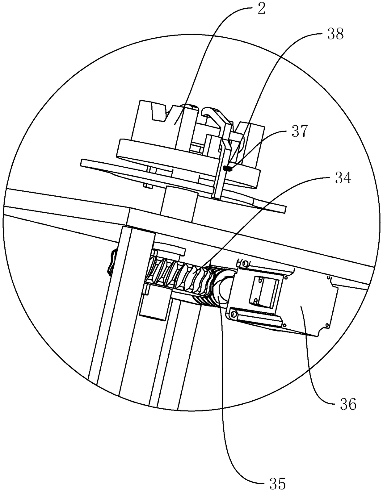
[0035] Embodiment 2, a kind of easy and simple clamping mechanism special for steel pipe, such as Figure 4 As shown, the difference from Embodiment 1 is that the driving member 3 includes a driving cylinder 39 fixed on the frame 1 perpendicular to the horizontal plane, and the output shaft of the driving cylinder 39 is provided with several linkages hinged to the corresponding jaws 24. Rod 391, one end of linkage rod 391 is hinged on the jaw 24, and the other end is hinged on the output shaft of the driving cylinder 39. The clamping jaws 24 are arranged in a corner shape, and the middle position of the clamping jaws 24 is connected to the fixed disk 2 , and the position of the clamping jaws 24 corresponding to the rolling wheel 23 is provided with a clamping groove 22 .

[0036] The output shaft of the cylinder moves, which drives the linkage rod 391 to move, thereby pulling the jaws 24 to rotate around the hinge shaft, thereby completing the clamping and loosening of the ste...


PUM


Abstract

The invention discloses a simple clamping mechanism special for a steel pipe. The simple clamping mechanism special for the steel pipe has the advantages that the steel pipe can be fixed firmly, and offset of the steel pipe in the welding process is reduced, so that the steel pipe welding error is reduced. According to the key points of the technical scheme, the simple clamping mechanism comprisesa rack, the rack is provided with a fixing disc, two clamping plates arranged mutually parallelly are fixed to the fixing disc and provided with clamping grooves correspondingly, and the clamping grooves are used for accommodating the steel pipe; a rolling wheel is rotationally connected between the two clamping plates, the fixing disc is provided with a plurality of clamping claws rotationally connected to the fixing disc, and the clamping claws are arranged corresponding to the rolling wheel and used for clamping the steel pipe in the clamping grooves; and the rack is provided with a driving piece used for driving the multiple clamping claws to synchronously rotate towards the clamping grooves, an operator can clamp and fix the steel pipe conveniently, offset of the steel pipe in the welding or cutting process is reduced, and the error of steel pipe connecting or cutting operation is reduced.

Description

technical field [0001] The invention relates to the field of scaffold manufacturing equipment, in particular to a simple and special clamping mechanism for steel pipes. Background technique [0002] Scaffolding is a working platform set up to ensure the smooth progress of various construction processes. According to the erection position, it can be divided into external scaffolding and internal scaffolding; according to different materials, it can be divided into wooden scaffolding, bamboo scaffolding and steel pipe scaffolding; according to the structure form, it can be divided into vertical pole scaffolding, bridge scaffolding, portal scaffolding, suspension scaffolding Hanging scaffolding, picking scaffolding, climbing scaffolding. [0003] With the emergence of a large number of modern large-scale building systems in our country, the fastener-type steel pipe scaffolding can no longer meet the needs of building construction development. It is urgent to vigorously develop...

Claims


Application Information

Patent Timeline
IPC IPC(8): B23K37/053B23Q3/08B23Q1/26
CPCB23K37/0533B23Q1/26B23Q3/064B23Q3/08B23Q2703/04
Inventor 黄国庆
Owner WUXI SAFETY SCAFFOLDING
Learn More