
A rectifier bridge frame with square contact surface and preparation method thereof

A contact surface and rectifier bridge technology, which is applied in semiconductor/solid-state device manufacturing, semiconductor/solid-state device parts, semiconductor devices, etc., can solve problems such as easy sliding of chips, chip offset, and large welding contact resistance, etc., to improve welding Effective area effect

Active Publication Date: 2020-01-17
四川旭茂微科技有限公司
View PDF5 Cites 0 Cited by
  • Summary
  • Abstract
  • Description
  • Claims
  • Application Information

AI Technical Summary

Problems solved by technology

[0006] The purpose of the present invention is to provide a rectifier bridge frame with a square contact surface and its preparation method, to solve the problem in the prior art that the frame and GPP chip welding area is too small to solve the problem of high welding contact resistance and energy consumption of the product. High, the problem of poor thermal conductivity of the product, and the problem that the round solder contact chip is easy to slide and cause the chip to shift

Method used


Image

  • A rectifier bridge frame with square contact surface and preparation method thereof
  • A rectifier bridge frame with square contact surface and preparation method thereof
  • A rectifier bridge frame with square contact surface and preparation method thereof

Examples


Embodiment Construction

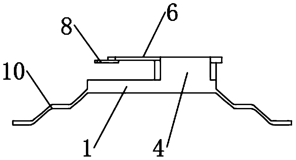
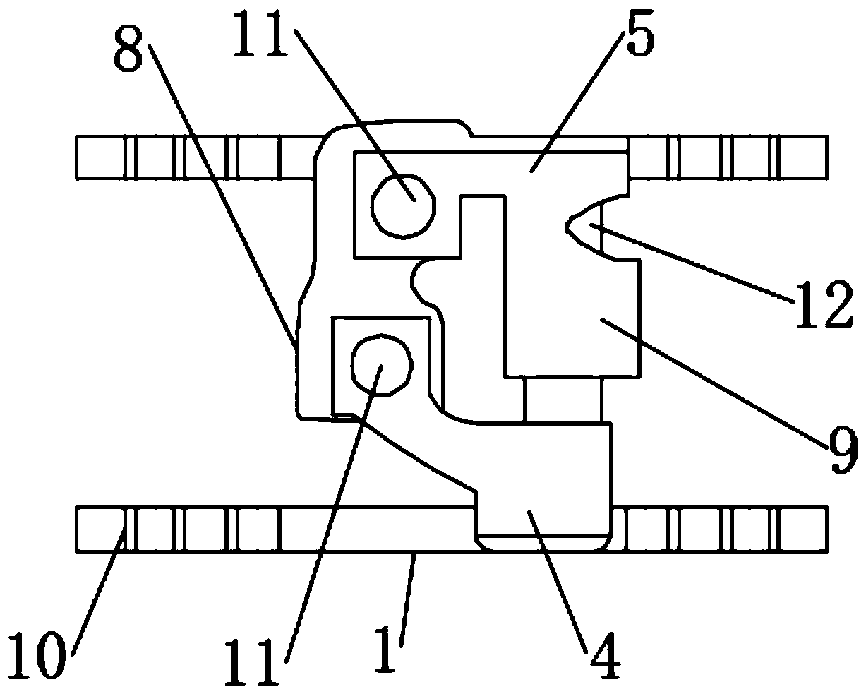
[0028] The following will clearly and completely describe the technical solutions in the embodiments of the present invention with reference to the accompanying drawings in the embodiments of the present invention. Obviously, the described embodiments are only some, not all, embodiments of the present invention. The specific embodiments described here are only used to explain the present invention, not to limit the present invention. Based on the embodiments of the present invention, all other embodiments obtained by persons of ordinary skill in the art without making creative efforts belong to the protection scope of the present invention.

[0029] The present invention provides such Figure 1-3 The shown rectifier bridge frame with a square contact surface includes a left frame 1 and a right frame 2, the left frame 1 and the right frame 2 are connected by a connecting plate 3, and the left frame 1 and the right frame 2 are connected by The plate 3 is arranged symmetrically ...


PUM


Abstract

The invention discloses a rectifier bridge framework with a square contact surface. The rectifier bridge framework comprises a left framework and a right framework, wherein the left framework is connected with the right framework through a connection plate; the left framework and the right framework are symmetrically arranged about the connection plate used as a center, and the left framework andthe right framework are of the same specification; and a left elastic sheet is arranged on the left framework, and a right elastic sheet corresponding to the left elastic sheet is arranged on the right elastic framework. According to the rectifier bridge framework with the square contact surface, by the adding of a supporting plate on the framework, the contact surface of the supporting plate is square and is matched with a welding plane of a chip; in a welding process, chip deviation can be avoided, and a certain deviation correction effect can be achieved on the chip deviation in a crystallization process; more effective supports are provided for welding of the square supporting plate to the contact surface framework under the same cross sectional area, so that the effective area of welding is enlarged.

Description

technical field [0001] The invention belongs to the technical field of rectifier bridges, in particular to a rectifier bridge frame with a square contact surface, and also relates to a preparation method for a rectifier bridge frame with a square contact surface. Background technique [0002] The rectifier bridge is to seal the rectifier tube in a shell, which is divided into full bridge and half bridge. The full bridge is to seal the four diodes of the connected bridge rectifier circuit together, and the half bridge is to seal the half of the four diode bridge rectifiers together. Two half bridges can be used to form a bridge rectifier circuit. The bridge can also form a full-wave rectification circuit with a center tap of the transformer, and the rectification circuit and operating voltage should be considered when selecting a rectifier bridge. [0003] The rectifier bridge is usually connected by two or four rectifier silicon chips, two of which are called half bridges, ...

Claims


Application Information

Patent Timeline
Patent Type & Authority Patents(China)
IPC IPC(8): H01L23/495H01L21/48
CPCH01L21/4842H01L23/49503H01L23/49541
Inventor 贺国东王秋明赵文全曾小容刘燕娟
Owner 四川旭茂微科技有限公司
Learn More