Rotary shaft and position-independent geometric error identification method based on ball-bar measurement
A technology of geometric error and identification method, which is applied in the direction of measuring/indicating equipment, metal processing machinery parts, metal processing equipment, etc., can solve the problem of few fast and effective detection methods
- Summary
- Abstract
- Description
- Claims
- Application Information
AI Technical Summary
Problems solved by technology
Method used
Image
Examples
Embodiment Construction
[0071] The present invention will be further described below in conjunction with the accompanying drawings and specific embodiments.
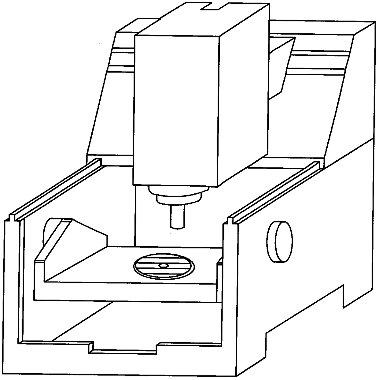
[0072] attached figure 1 Shown is a schematic structural diagram of a five-axis CNC machine tool, and the method of the present invention is described by taking the machine tool as an example.
[0073] In step 1, determine the measurement position of the ballbar according to the structure of the machine tool and the type of the rotary axis. Install the spindle tool cup and the base tool cup, and perform calibration, including steps:
[0074] Step 1.1. Determine the rotary axis type of the machine tool as A-axis and C-axis, and define the reference coordinate system as the intersection of the A-axis rotary center and the C-axis rotary center under ideal conditions.
[0075] Step 1.2. Determine the installation positions of the spindle tool cup and the base tool cup. When measuring the A-axis, the ballbar base is installed on the A-axis turnt...
PUM
 Abstract
Description
Claims
Application Information
 - R&D
- Intellectual Property
- Life Sciences
- Materials
- Tech Scout
- Unparalleled Data Quality
- Higher Quality Content
- 60% Fewer Hallucinations
Browse by: Latest US Patents, China's latest patents, Technical Efficacy Thesaurus, Application Domain, Technology Topic, Popular Technical Reports.
© 2025 PatSnap. All rights reserved.Legal|Privacy policy|Modern Slavery Act Transparency Statement|Sitemap|About US| Contact US: help@patsnap.com


