Secondary dust-removal equipment used for separating fine particulate matter dust in tail gas

A technology for fine particles and secondary dust removal, applied in separation methods, dispersed particle separation, chemical instruments and methods, etc., can solve problems such as difficult handling, poor fire safety, and restrictions on use occasions, and achieve space saving, resistance reduction, and energy saving The effect of investment

Pending Publication Date: 2018-11-02
NANJING LONGYUAN ENVIRONMENTAL CO LTD
View PDF8 Cites 0 Cited by
  • Summary
  • Abstract
  • Description
  • Claims
  • Application Information

AI Technical Summary

Problems solved by technology

[0004] Facing the reality that the industry’s pollutant emission standards are about to be upgraded, conventional centrifugal force dust removal, filter dust removal and other dust removal devices cannot directly achieve the ultra-low emission requirements of ≤10mg / m³, and bag dust removal is difficult due to high temperature, high relative humidity, and high viscosity dust. processing, and the fire safety is poor, and the use occasions are limited

Method used


Image

  • Secondary dust-removal equipment used for separating fine particulate matter dust in tail gas
  • Secondary dust-removal equipment used for separating fine particulate matter dust in tail gas

Examples


Embodiment 1

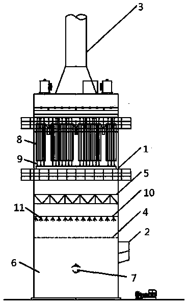
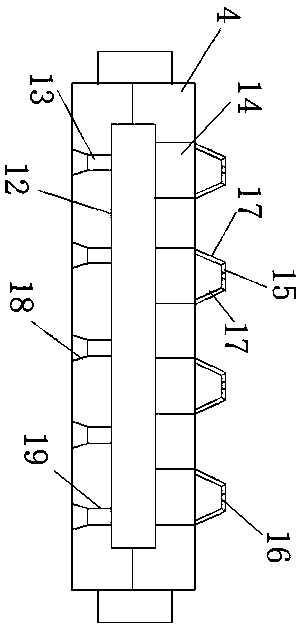
[0026] It can be seen from the accompanying drawings that a secondary dedusting equipment for separating fine particle dust in exhaust gas includes a tower body 1, and a spray dedusting device and a wet electrostatic dedusting device are arranged in the tower body 1 sequentially from bottom to top. The left end of the tower body 1 is provided with a flue gas inlet 2, and the upper end of the tower body 1 is provided with a flue gas outlet 3. The spray dust removal device includes an air distribution plate 4, a first spray device and a demisting device arranged in sequence from bottom to top. A waste water recovery tank 6 is arranged under the air distribution plate 4, the flue gas inlet 2 is arranged between the air flow distribution plate 4 and the waste water recovery tank 6, and an overflow tank 7 is arranged on the waste water recovery tank 6 .

Embodiment 2

[0028] As an improvement of the present invention, the wet electrostatic precipitator includes an anode tube 8, a cathode line 9 and a second spray device, the upper and lower ends of the anode tube 8 are connected to the tower body 1, and each cathode line 9 all pass through an anode tube 8 correspondingly, and the cathode line 9 is connected to the tower body 1 by hanging in the air, and a second spraying device is arranged above the anode tube 8 and the cathode line 9 .

[0029] The rest of the structural features and advantages are exactly the same as in Embodiment 1.

Embodiment 3

[0031] As an improvement of the present invention, the first spraying device includes a spraying pipeline 10, a water tank, a pump and a spraying head 11, the water tank is connected to the spraying pipeline 10 through a pump, and the spraying pipeline 10 is provided with There are shower heads 11, and the number of said shower heads 11 is at least two. All the other structures and advantages are identical to Embodiment 1.


PUM


Abstract

The invention relates to secondary dust-removal equipment used for separating fine particulate matter dust in tail gas. The secondary dust-removal equipment is characterized by comprising a tower body, wherein a spraying and dust-removing device, and a wet-electric dust-removing device are sequentially arranged in the tower body from bottom to top; the left end of the tower body is equipped with aflue gas inlet; the upper end of the tower body is equipped with a flue gas outlet; the spraying and dust-removing device comprises a gas flow distributing plate, a spraying device and a de-mister which are sequentially arranged from bottom to top; a wastewater recycling box is arranged below the gas flow distributing plate; the flue gas inlet is formed between the gas flow distributing plate andthe wastewater recycling box; and an overflow slot is formed in the wastewater recycling box. According to the secondary dust-removal equipment disclosed by the invention, the spraying and dust-removing device and the wet-electric dust-removing device are combined in series for use, so that graded treatment and efficient removal on liquid-state or solid-state particles and gas-phase pollutants are realized.

Description

technical field [0001] The invention relates to secondary dedusting equipment for separating fine particle dust in tail gas, belonging to the field of dedusting equipment. Background technique [0002] At present, the emission of air pollutants in the domestic wood-based panel industry requires that the allowable emission concentration of particulate matter is 150 mg / m³. This standard was formulated based on the technical level in the 1990s, and it is now significantly behind. [0003] The existing environmental department stipulates that the particulate matter emission limit set by different production processes and product characteristics of wood-based panels is 10-20mg / m³ (10mg / m³ for drying after sizing and the tail gas of the mixing process), and also stipulates special emission limits for environmentally sensitive areas 5-10mg / m³ (5mg / m³ for drying after sizing and tail gas of mixing process). [0004] Faced with the reality that the industry’s pollutant discharge sta...

Claims


Application Information

Patent Timeline
Patent Type & Authority Applications(China)
IPC IPC(8): B01D50/00
CPCB01D50/00
Inventor 王生公惠斌孙卫东
Owner NANJING LONGYUAN ENVIRONMENTAL CO LTD
Why Eureka
Try Eureka