
Casting process for directional control valve

A directional control valve and casting process technology, applied in manufacturing tools, casting molding equipment, casting molds, etc., to avoid overheating, ensure appearance quality, and ensure product dimensional accuracy.

Inactive Publication Date: 2018-10-30
如皋岩达机械工业有限公司
View PDF0 Cites 2 Cited by
  • Summary
  • Abstract
  • Description
  • Claims
  • Application Information

AI Technical Summary

Problems solved by technology

[0004] The above-mentioned directional control valve is mainly integrally formed by casting, and there are two difficulties in the casting process: one is how to improve the cutting performance of the product while increasing the hardness of the casting product; the other is how to form a high-precision flow channel and ensure the straight line of the flow channel Accuracy of degrees and notch dimensions

Method used


Image

  • Casting process for directional control valve
  • Casting process for directional control valve

Examples


Embodiment 1

[0035] The invention provides a manufacturing process of a directional control valve, which mainly includes the following steps:

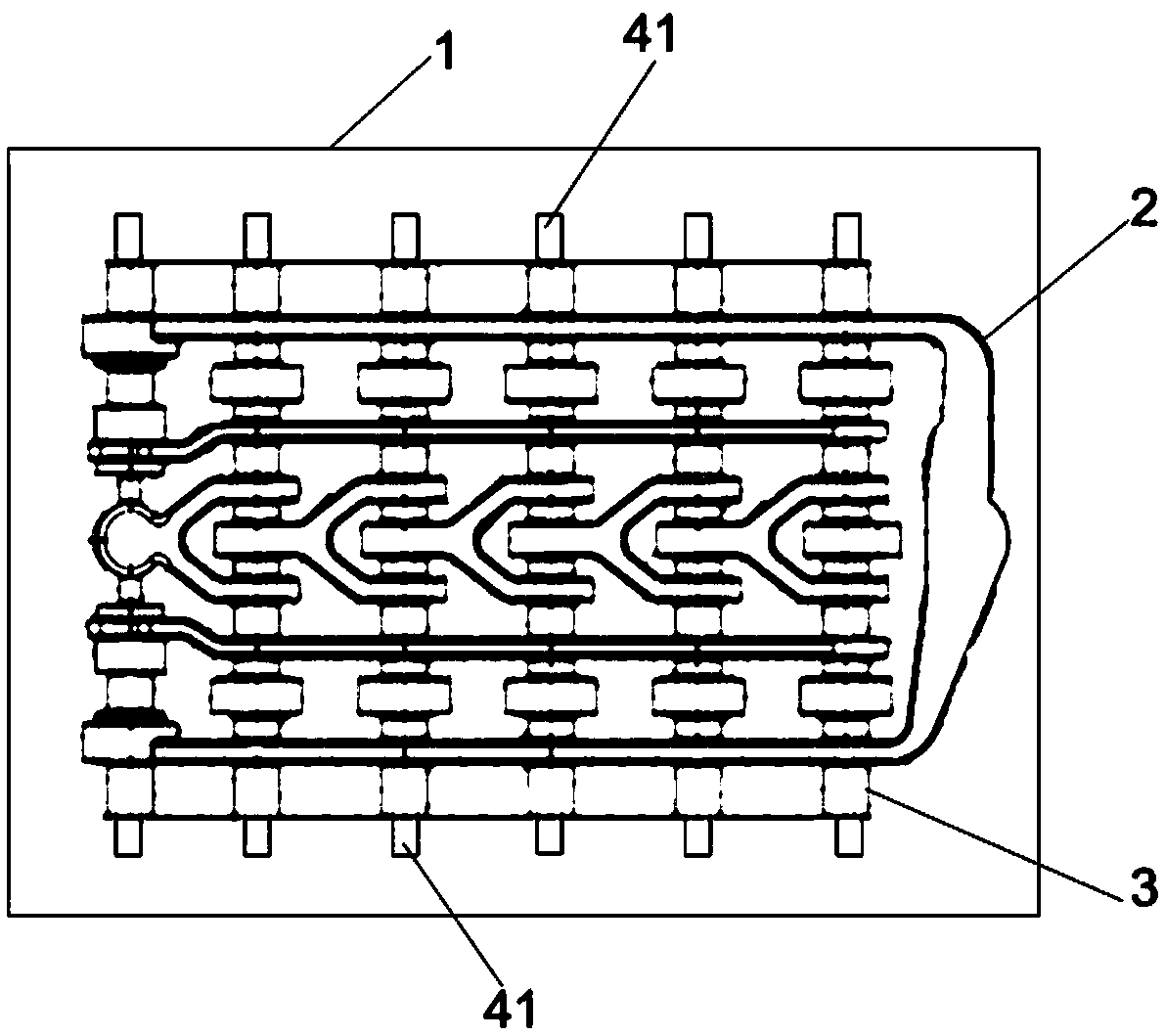
[0036] S1, molding process (as shown in the figure and figure 2 As shown): make a shell 1, and set a gate with a height of 8 mm and a length of 30 mm on the side of the shell 1; use resin sand molding to make a clay core 2, and set a core bone 4 in the clay core 2 and the ventilation needle 5, and the ventilation needle 5 is set away from the mandrel 4, and the mandrel 4 is made of steel pipe; the mud core 2 is polished after being made, and the two sides of the sand core 2 after polishing The core bone protruding part 41 is provided at the end; the mud core 2 is placed horizontally in the shell 1, and the core bone protruding part 41 is overlapped with the inside of the shell 1; the specific connection structure As follows: the top of the shell 1 is provided with a thermal insulation riser, the shell 1 includes an upper shell and a lower shell, ...

Embodiment 2

[0041] The invention provides a manufacturing process of a directional control valve, which mainly includes the following steps:

[0042] S1, molding process (as shown in the figure and figure 2 As shown): make a shell 1, and set a gate with a height of 8 mm and a length of 30 mm on the side of the shell 1; use resin sand molding to make a clay core 2, and set a core bone 4 in the clay core 2 and the ventilation needle 5, and the ventilation needle 5 is set away from the mandrel 4, and the mandrel 4 is made of steel pipe; the mud core 2 is polished after being made, and the two sides of the sand core 2 after polishing The core bone protruding part 41 is provided at the end; the mud core 2 is placed horizontally in the shell 1, and the core bone protruding part 41 is overlapped with the inside of the shell 1; the specific connection structure As follows: the top of the shell 1 is provided with a thermal insulation riser, the shell 1 includes an upper shell and a lower shell, ...

Embodiment 3

[0047] The invention provides a manufacturing process of a directional control valve, which mainly includes the following steps:

[0048] S1, molding process (as shown in the figure and figure 2 As shown): make a shell 1, and set a gate with a height of 8 mm and a length of 30 mm on the side of the shell 1; use resin sand molding to make a clay core 2, and set a core bone 4 in the clay core 2 and the ventilation needle 5, and the ventilation needle 5 is set away from the mandrel 4, and the mandrel 4 is made of steel pipe; the mud core 2 is polished after being made, and the two sides of the sand core 2 after polishing The core bone protruding part 41 is provided at the end; the mud core 2 is placed horizontally in the shell 1, and the core bone protruding part 41 is overlapped with the inside of the shell 1; the specific connection structure As follows: the top of the shell 1 is provided with a thermal insulation riser, the shell 1 includes an upper shell and a lower shell, ...


PUM

PropertyMeasurementUnit
particle sizeaaaaaaaaaa
heightaaaaaaaaaa
lengthaaaaaaaaaa

Abstract

The invention discloses a casting process for a directional control valve. The casting process comprises a modeling procedure, a molten metal smelting procedure, a casting forming procedure and a casting treatment procedure. According to the modeling procedure, a shell and a loam core are manufactured, and the loam core is internally provided with an arbor and a vent wire; after being manufactured, the loam core is polished, and the two ends of the polished loam core are provided with arbor protruding parts; and the loam core is horizontally arranged in the shell, and the arbor protruding parts are connected with the interior of the shell in an overlapped manner. According to the molten smelting procedure, raw materials are put into a smelting furnace to be smelted, and then a nodulizing agent and a nucleating agent are sequentially added. The nucleating agent is composed of a silicon and strontium nucleating agent and a silicon and rare earth nucleating agent, the weight percent of the silicon and strontium nucleating agent is 0.2%-0.4%, the particle size of the silicon and strontium nucleating agent is 2 mm-6 mm, the weight percent of the silicon and rare earth nucleating agent is 0.1%-0.3%, and the particle size of the silicon and rare earth nucleating agent 2 mm-6 mm. According to the casting forming procedure, water enters from a lateral sprue. According to the casting treatment procedure, a casting is subjected to polishing and heat treatment. According to the casting process, the cutting performance of the product can be improved while the hardness of the casting product is improved, a high-precision runner can be formed, and the straightness of the runner and the gear size precision are guaranteed.

Description

technical field [0001] The invention relates to the technical field of casting, in particular to a casting process of a directional control valve. Background technique [0002] Directional control valve is a control element used to change the flow direction of gas or liquid in the pipeline. With the development of hydraulic technology, high pressure and large flow have always been an important direction for the development of the hydraulic industry. In recent years, with the increasing tonnage of construction machinery, the hydraulic system of agricultural machinery has higher and higher requirements for directional control valves. [0003] The Bondioli&Pavesi group company was established in Suzzara, Italy in 1950, and in just a few years it has taken a leading position in the field of drive shafts in the world. Bondioli&Pavesi Group is the first in Italy to provide complete transmission systems in agricultural machinery and equipment, and is constantly expanding its rang...

Claims


Application Information

Patent Timeline
Patent Type & Authority Applications(China)
IPC IPC(8): B22C9/24B22C9/10B22C9/02C22C33/08
CPCB22C9/24B22C9/02B22C9/106C22C33/08
Inventor 石慧亮
Owner 如皋岩达机械工业有限公司
Learn More