
Vertical vacuum crystallization device

A vacuum crystallization, vertical technology, applied in the general layout of the crystallization device, solution crystallization, evaporation separation crystallization, etc., can solve the problems of affecting the growth of other crystals, poor mixing degree of slurry, and easy scaling of cooling pipes, etc. Achieve the effects of increasing evaporation intensity, adjusting production load, and reducing the probability of collision, fragmentation and nucleation

Pending Publication Date: 2018-10-30
JIANGSU XINHONGDA GROUP
View PDF7 Cites 4 Cited by
  • Summary
  • Abstract
  • Description
  • Claims
  • Application Information

AI Technical Summary

Problems solved by technology

[0008] (5) Elimination of fine crystals. There are too many fine crystals in the magma, which over-digests the supersaturation of the solution, affects the growth of other crystals, and is not conducive to the separation of subsequent processes, and is too small for commercial use. It needs to inject decrystallization water to dissolve Fine crystals to control particle number density and produce coarser crystal products
The forced circulation evaporation crystallizer has a large production capacity, but because there is no stirring device inside the crystallizer, the mixing degree of the slurry becomes poor, resulting in a wide particle size distribution of the product; and because of the external circulation cooling in the equipment, the cooling pipe will be easier to scale

Method used


Image

  • Vertical vacuum crystallization device

Examples


Embodiment Construction

[0033] In order to have a further understanding of the purpose, structure, features, and functions of the present invention, the following detailed descriptions are provided in conjunction with the embodiments.

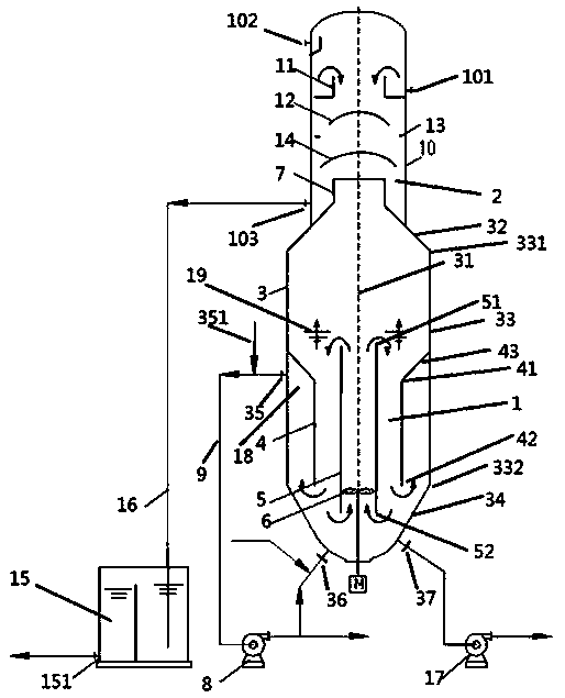
[0034] see figure 1 , figure 1 It is a schematic diagram of the overall structure of a vertical vacuum crystallization device of the present invention, as figure 1 As shown, the vertical vacuum crystallization device according to an embodiment of the present invention includes a crystallization part 1 and a condensation part 2 .

[0035]The crystallization section 1 includes a crystallization section cylinder body 3, an outer guide cylinder 4, a central guide cylinder 5, a bottom agitator 6, a secondary steam ascending cylinder 7, a circulation pump 8, an inner circulation channel and an outer circulation channel.

[0036] The crystallization section barrel 3 is an axisymmetric structure with a central axis 31, comprising successively connected truncated conical upp...


PUM


Abstract

The invention provides a vertical vacuum crystallization device. The vertical vacuum crystallization device comprises a crystallization part and a condensing part, wherein the crystallization part islocated below the condensing part and comprises a crystallization section cylinder, an outer flow guiding cylinder, a central flow guiding cylinder, a bottom stirrer, a secondary stream rising cylinder, a circulating cylinder, an inner circulating channel and an outer circulating channel; and the condensing part comprises a condensing section cylinder as well as an overflow weir, a first water baffling cap, a liquid baffling ring and a second water baffling cap which are sequentially arranged in the condensing section cylinder from top to bottom. The vertical vacuum crystallization device hasthe advantages that a heat exchanger does not need to be replaced, and the problems that the inner surface is seriously scaled, and the scale is difficult to clean are prevented; an vacuum processingpressure is similar to a solution steam partial pressure, and the operation is relatively stable; the crystallization part and the condensing part form equipment, so that a secondary steam flow path is shortened, and the leakage of leaking points caused due to the connection of pipelines is eliminated; by utilizing the inner circulating channel, the high-saturability region in the crystallizationpart is eliminated, and the saturability at each site is relatively uniform and low; and by utilizing the outer circulating channel, the excess crystallization is eliminated; and meanwhile, products with relatively narrow particle size distribution can be elutriated.

Description

technical field [0001] The invention relates to the field of chemical separation, in particular to a vertical vacuum crystallization device. Background technique [0002] Crystallization refers to the process in which a solid is precipitated from a gas, liquid or melt in a crystalline state. This process is determined by thermodynamic and kinetic factors. To precipitate a solute from a solution, it must continuously obtain energy from the outside to keep the solution in the solution. Evaporate to make it saturated and supersaturated. When the solution is not saturated (in the stable zone), the solute will not crystallize. When the solution is between the solubility curve and the supersolubility curve (metastable zone), the solute crystallizes and The dissolution is in a dynamic equilibrium, solutes will not spontaneously nucleate and precipitate, and crystals will grow if there are crystal nuclei entering. This stage is very susceptible to external influences, that is, wheth...

Claims


Application Information

Patent Timeline
Patent Type & Authority Applications(China)
IPC IPC(8): B01D9/02
CPCB01D9/0018B01D9/0059
Inventor 陈爱民沈梅和
Owner JIANGSU XINHONGDA GROUP
Learn More