
Rotor punching plate adapting to high-speed rotation

A technology of rotor punching and high-speed rotation, applied in the direction of magnetic circuit rotating parts, electrical components, electromechanical devices, etc., can solve problems such as magnetic bridge damage, achieve smooth contours, ensure magnetic flux leakage, and improve molding rates.

Inactive Publication Date: 2018-10-26
广州精传科技有限公司
View PDF3 Cites 3 Cited by
  • Summary
  • Abstract
  • Description
  • Claims
  • Application Information

AI Technical Summary

Problems solved by technology

[0004] The present invention intends to provide a rotor stamping adapted to high-speed rotation to solve the problem in the prior art that the magnetic bridge of the rotor stamping is easily damaged under high-speed rotation

Method used


Image

  • Rotor punching plate adapting to high-speed rotation
  • Rotor punching plate adapting to high-speed rotation

Examples


Embodiment Construction

[0011] The following is further described in detail through specific implementation methods:

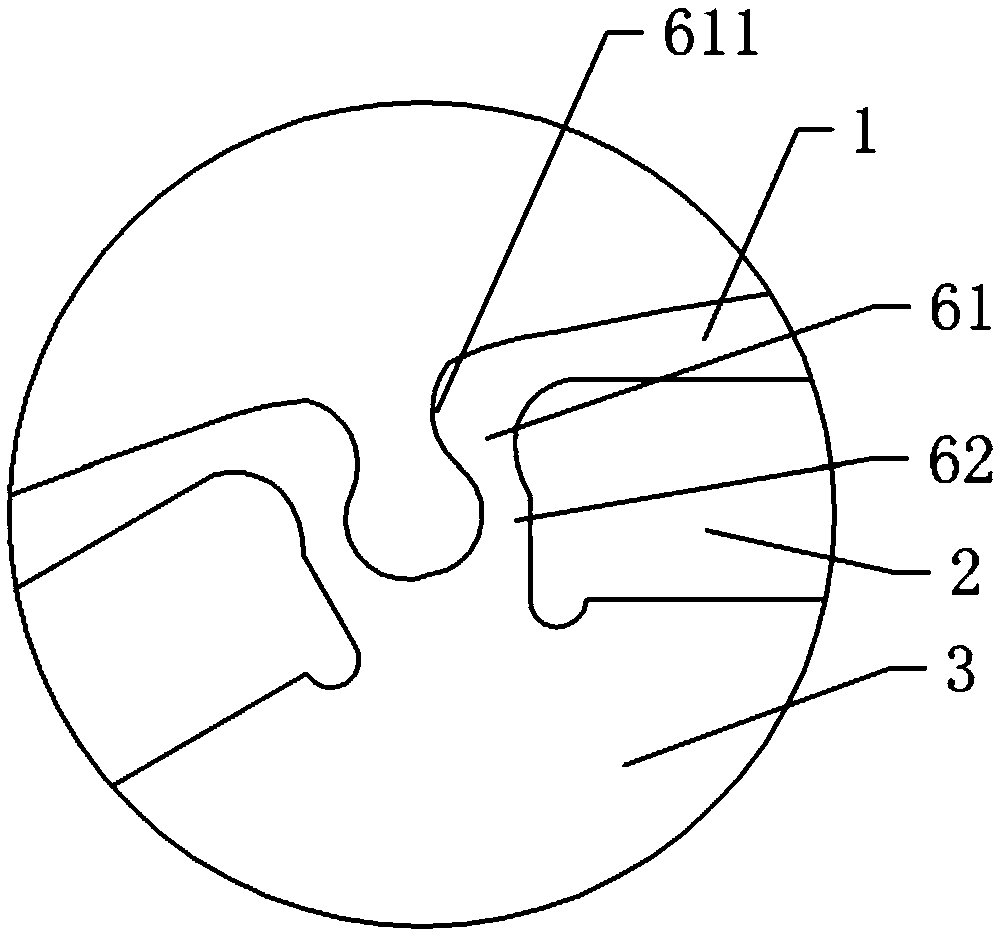
[0012] The reference signs in the drawings of the description include: cover plate 1 , magnetic steel placement cavity 2 , punch body 3 , weight reduction hole 4 , connection hole 5 , reinforcement section 61 , raised portion 611 , and straight section 62 .

[0013] The embodiment is basically as attached figure 1 and figure 2 As shown: a rotor punching plate adapted to high-speed rotation, including a punching plate body 3, and a connecting hole 5 with a keyway is arranged in the middle of the punching body 3 along the axial direction. The punch body 3 is also provided with 12 weight-reducing holes 4 , and all the weight-reducing holes 4 are distributed in an annular array with the axis of the punch body 3 as the central axis. The edge of the punching body 3 is provided with 12 bar-shaped magnetic steel placement cavities 2, and all the magnetic steel placement cavities 2 are arr...


PUM


Abstract

The invention relates to the technical field of rotating parts of magnetic circuits, in particular to a rotor punching plate adapting to high-speed rotation. The rotor punching plate comprises a punching plate body, wherein a magnetic steel placement cavity is arranged on the edge of the punching plate body; a magnetic bridge is arranged at the end part of the magnetic steel placement cavity; themagnetic bridge is sequentially provided with a straight section and a reinforcing section along the length direction; the side, toward the magnetic steel placement cavity, of the straight section isa straight edge; one side, toward the magnetic steel placement cavity, of the reinforcing section is arranged in a rounded manner; a boss is arranged at one side, back to the magnetic steel placementcavity, of the reinforcing section; and the width of the reinforcing section is gradually increased from one end close to the straight section to one end far away from the straight section. Accordingto the rotor punching plate, the problem that the magnetic bridge of the rotor punching plate is easily damaged under the condition of high-speed rotation in the prior art is solved.

Description

technical field [0001] The invention relates to the technical field of rotating components of a magnetic circuit, in particular to a rotor punching plate adapted to high-speed rotation. Background technique [0002] Now there are higher and higher requirements for the efficiency of new energy vehicle motors. It is hoped that the motors will have higher power density and higher efficiency. The wider the high-efficiency range, the better. In order to adapt to the characteristics of small volume, small moment of inertia, fast dynamic response and good peak speed performance of the new energy vehicle motor, higher requirements are put forward for the speed of the motor. Therefore, as the speed of the motor increases, higher requirements are placed on the strength design and reliability of the rotor punch. [0003] The edge of the rotor punching sheet of the motor is provided with a magnet steel placement cavity inside, and the magnet steel placement cavity is provided with a ma...

Claims


Application Information

Patent Timeline
Patent Type & Authority Applications(China)
IPC IPC(8): H02K1/27
CPCH02K1/274
Inventor 王迪赖楚项钟少武
Owner 广州精传科技有限公司
Learn More