
A monitoring device and system for breathing frequency, a respirator and an oxygen uptake machine

A breathing frequency and monitoring device technology, applied in the field of sensors, can solve the problem that the equipment cannot monitor the user's breathing frequency sensitively and accurately, and achieve the effect of being suitable for large-scale industrial production, simple in structure and manufacturing process, and high in sensitivity and accuracy

Pending Publication Date: 2018-10-26
NAZHIYUAN TECH TANGSHAN LLC
View PDF7 Cites 4 Cited by
  • Summary
  • Abstract
  • Description
  • Claims
  • Application Information

AI Technical Summary

Problems solved by technology

[0006] The purpose of the present invention is to address the defects of the prior art and provide a respiratory frequency monitoring device, system, ventilator and oxygen inhaler to solve the problem that the equipment in the prior art cannot monitor the user's respiratory rate sensitively and accurately. The problem

Method used


Image

  • A monitoring device and system for breathing frequency, a respirator and an oxygen uptake machine
  • A monitoring device and system for breathing frequency, a respirator and an oxygen uptake machine
  • A monitoring device and system for breathing frequency, a respirator and an oxygen uptake machine

Examples


example 1

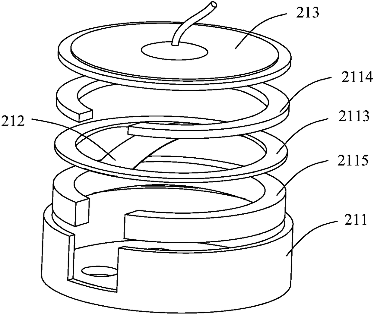
[0052] Figure 2a and Figure 2b They are respectively a three-dimensional structural schematic diagram and a cross-sectional structural schematic diagram of the first example of the pneumatic sensor in the first embodiment of the respiratory frequency monitoring device provided by the present invention. Such as Figure 2a and 2b As shown, the pneumatic sensor includes: a housing 211 , a diaphragm assembly 212 and an electrode assembly 213 . Wherein, an accommodating chamber is formed inside the housing 211, an air inlet 2111 is formed on the side wall of the housing 211, and at least one air outlet 2112 is formed on the bottom wall, and the air inlet 2111 and the air outlet 2112 are respectively connected to the housing. The chambers are connected to form an airflow passage, so that the airflow generated by the user’s inhalation or exhalation passes through the airflow passage; the two ends of the diaphragm assembly 212 are fixedly arranged in the accommodating chamber ins...

example 2

[0056] Figure 2c It is a schematic structural diagram of the second example of the pneumatic sensor in the first embodiment of the breathing frequency monitoring device provided by the present invention. Such as Figure 2c As shown, the pneumatic sensor includes: a shielding shell 221 , an insulating layer 222 disposed on part or all of the inner surface of the shielding shell 221 , and at least one sensing unit. Wherein, the shielding shell 221 is provided with at least two air vents 2211, and the airflow generated by the user's inhalation or exhalation passes between the at least two air vents 2211; One air vent 2211, the air flow can enter from one of the air vents 2211 and flow out from the other air vent 2211. The sensing unit includes: at least one fixed layer and one free layer; at least one fixed layer is fixed on the shielding shell 221; the free layer has a fixed part and a friction part; the fixed part of the free layer is connected with at least one fixed layer ...

example 3

[0059] Figure 2d It is a schematic structural diagram of Example 3 of the pneumatic sensor in Example 1 of the respiratory frequency monitoring device provided by the present invention. Such as Figure 2d As shown, the pneumatic sensor includes: a casing 231 , and a first polymer film 233 , a support structure 234 and an electrode 232 sequentially arranged inside the casing 231 . Wherein, the support structure 234 is disposed outside the electrode 232 , and the first polymer film 233 is sheathed outside the electrode 232 and the support structure 234 . Wherein, the casing 231 is a hollow structure, and the electrode 232 and the first polymer film 233 are set inside. The central axes of the shell 231 , the electrode 232 and the first polymer film 233 are located on the same straight line, and the surfaces of the three are separated from each other. In terms of material, the housing 231 can be a metal shell, or a non-metal insulating shell. Structurally, the housing 231 fur...


PUM


Abstract

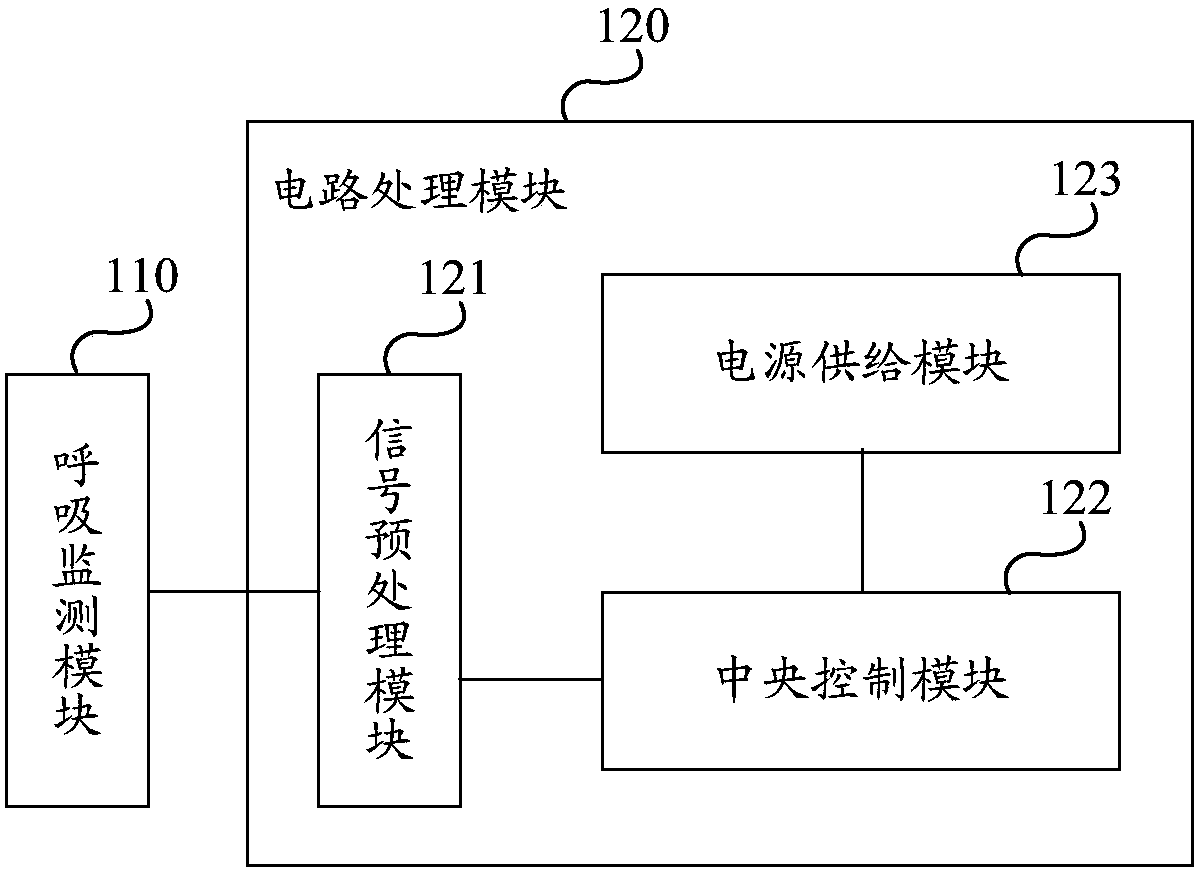
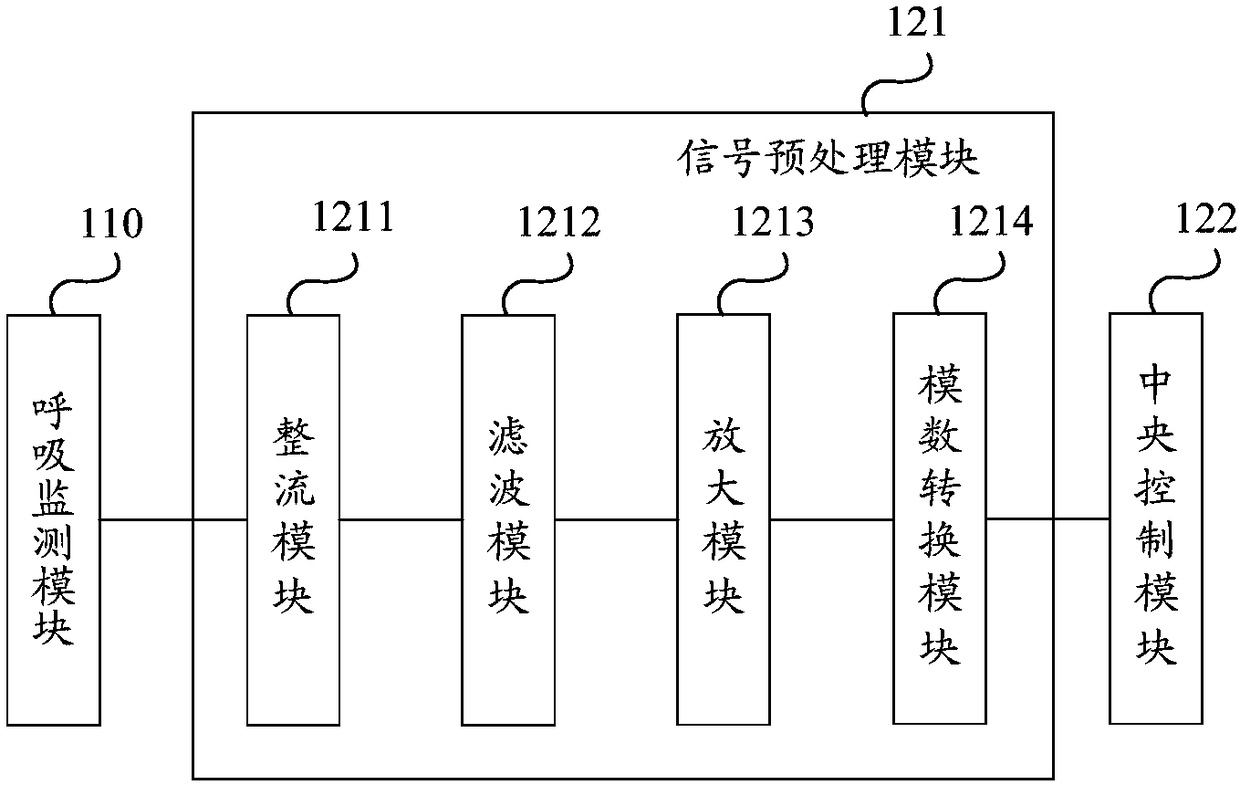
The invention discloses a monitoring device and system for breathing frequency, a respirator and an oxygen uptake machine. The monitoring device for breathing frequency includes a breathing monitoringmodule and an electric circuit processing module, and the electric circuit processing module includes a signal preprocessor module, a central control module, and a power supply module, wherein the breathing monitoring module is used for outputting a breathing electric signal according to the air flow generated by the inhalation or expiration of users; the signal preprocessor module is electrically connected with the breathing monitoring module, and is used for performing pretreatment on the breathing electric signal outputted from the breathing monitoring module; the central control module iselectrically connected with the signal preprocessor module, and is used for analyzing and calculating the breathing frequency of a user in a first preset time interval according to the breathing electrical signal pretreated by the signal preprocessor module; the power supply module is electrically connected with the central control module, and is used for providing electric energy. The breathingfrequency of users can be sensitively and accurately monitored by the monitoring device and system for breathing frequency, the respirator and the oxygen uptake machine.

Description

technical field [0001] The invention relates to the technical field of sensors, in particular to a breathing frequency monitoring device, a system, a ventilator and an oxygen inhaler. Background technique [0002] At present, among the seriously ill patients treated in the hospital, a large part of the patients have the risk of suffocation due to the disease itself, especially after such an incident occurs at night, it is often not discovered by the patient's family members and medical staff in time, and the best time is missed. Time to rescue. [0003] Even in the intensive care unit, due to related factors such as personnel and energy, the time interval for intensive care nurses to visit patients is at least 15 minutes. Although family members are nursing at the bedside, due to lack of professional knowledge, they often mistakenly compare breathing and heartbeat. Pause mistook it for falling asleep. However, the human brain has very poor tolerance to ischemia and hypoxia...

Claims


Application Information

Patent Timeline
Patent Type & Authority Applications(China)
IPC IPC(8): A61M16/00A61B5/08
CPCA61M16/0003A61B5/0816A61B5/746A61M2016/0027A61M2202/0208A61M2205/33A61M2205/3331A61M2205/18A61M2202/0007
Inventor 徐传毅
Owner NAZHIYUAN TECH TANGSHAN LLC
Learn More