
Device and method for quickly measuring performance of laser ranging system

A technology for measuring lasers and ranging systems, applied in measuring devices, radio wave measuring systems, electromagnetic wave re-radiation, etc., can solve the problems of low support efficiency, affecting the purpose of command operations, single function, etc., and achieve fast optical axis alignment , self-test method is simple, low-cost effect

Pending Publication Date: 2018-10-23
SHANGHAI INST OF TECHNICAL PHYSICS - CHINESE ACAD OF SCI
View PDF14 Cites 8 Cited by
  • Summary
  • Abstract
  • Description
  • Claims
  • Application Information

AI Technical Summary

Problems solved by technology

Especially in the current high-intensity actual combat training, once the laser ranging system fails, it will affect the command's combat purpose
Due to the inability to universally solve the detection and maintenance problems of laser ranging systems for infantry, artillery, armored troops, and sea defense island troops, the problems of detection and maintenance equipment with various types, single functions, large funds and resources, and low support efficiency have been difficult to solve for a long time

Method used

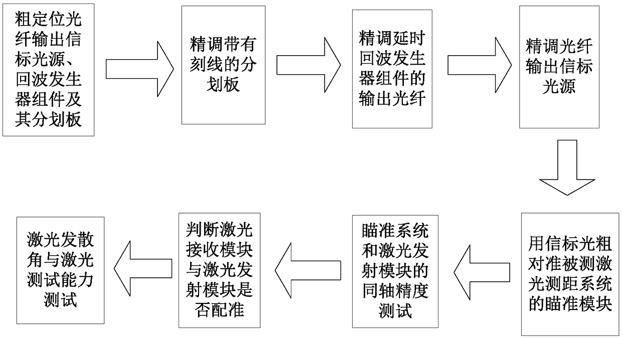

Image

  • Device and method for quickly measuring performance of laser ranging system
  • Device and method for quickly measuring performance of laser ranging system

Examples


Embodiment Construction

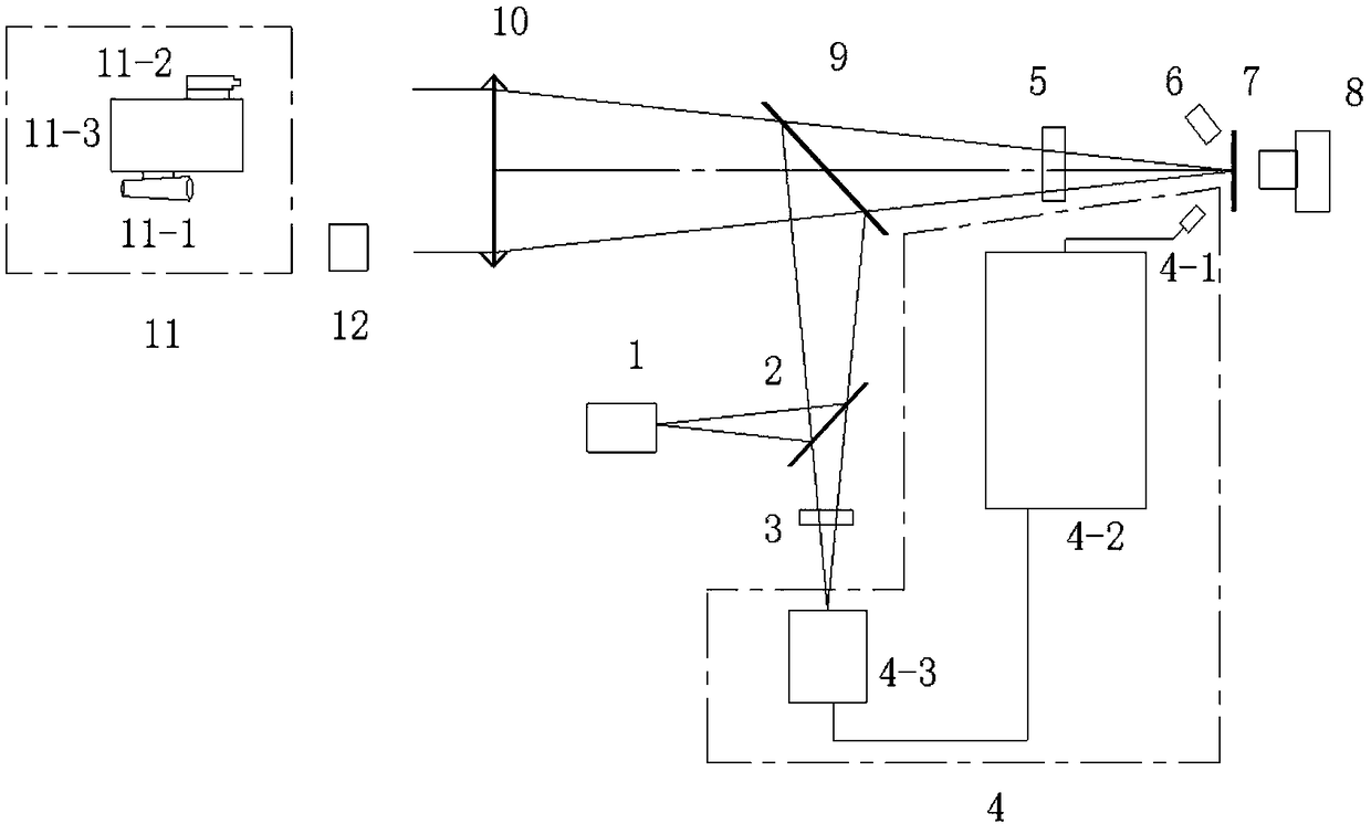
[0027] The implementation examples of the method of the present invention will be described in detail below in conjunction with the accompanying drawings.

[0028] The main devices adopted in the present invention are described as follows:

[0029] 1) Optical fiber output beacon light source 1: adopt the green laser of Changchun New Industry, the laser model is LFM520, and the output power is 2.5mw.

[0030] 2) Separation film 2: Thorlabs’ model is FGB25 color separation film. Its main performance parameters are: 532nm full reflection, 1064 semi-reflective and semi-transparent, clear aperture Φ25mm, surface shape better than λ / 10@632.8nm.

[0031] 3) Laser energy controllable attenuation device 3: The Thorlabs company model is NDC-25C-4, the attenuation efficiency is from 0 to (-40)db, and the diameter is Φ25mm

[0032]4) Delayed echo generator component 4: This device is a self-made device, mainly composed of a high-speed detector 4-1, a delayed echo generator 4-2 and a cont...


PUM


Abstract

The invention discloses a device and method for quickly measuring the performance of a laser ranging system. According to the device and method of the invention, a reticle with scribed lines and a laser optical fiber end surface are equidistantly fixed to two sides of a color separation film by means of the light splitting function of the color separation film; an optical fiber transmits laser generated by a delayed echo generator component to a device under test through a collimator; a beacon light source outputted from the optical fiber is arranged at the focal plane of the collimator so asto be adopted as indication light; and therefore, the rapid measurement of the performance of the laser ranging system can be realized. The device and method can be used for detecting a laser divergence angle and light spot energy in the laser ranging system and the ranging capability of the laser ranging system and can also be used for calibrating the optical axis deviation of the laser receivingand transmitting of the device under test. The device and method of the invention are applicable to the real-time calibration of the performance of various laser ranging systems, and are also applicable to the transmitting and receiving coaxial detection of an active and passive combined photoelectric system and other fields. According to the device and method of the invention, a focal plane module is fixed, a calibration method is simple, and prices are low.

Description

technical field [0001] The invention belongs to the field of optical detection technology, and in particular relates to a device and method for quickly measuring the performance of a laser ranging system, which is especially suitable for the rapid test requirements in the field of a laser ranging system composed of an aiming device, a laser emitting module, and a laser receiving module , various laser active and passive combination photoelectric system send and receive coaxial detection and other fields. Background technique [0002] The laser ranging system has now become an important part of the sighting and aiming instruments of various arms of the army; such as the main battle tanks of the armored forces, various types of gunner stabilized image sights of the mechanized infantry fighting vehicles, the commander's peripheral vision sights, and the sighting guidance instrument etc., the laser ranging system is a fast, accurate and convenient modern equipment that can reali...

Claims


Application Information

Patent Timeline
Patent Type & Authority Applications(China)
IPC IPC(8): G01S7/497G01S17/08
CPCG01S7/497G01S17/08
Inventor 何志平王天洪黄庚华吴金才舒嵘
Owner SHANGHAI INST OF TECHNICAL PHYSICS - CHINESE ACAD OF SCI
Learn More