Pressure sensor

A pressure sensor, pressure surface technology, applied in the direction of measuring fluid pressure, instruments, measuring fluid pressure through electromagnetic components, etc., can solve problems such as reduced reliability of measured pressure and diaphragm bending

Active Publication Date: 2018-10-23
HORIBA STEC CO LTD
View PDF7 Cites 3 Cited by
  • Summary
  • Abstract
  • Description
  • Claims
  • Application Information

AI Technical Summary

Problems solved by technology

As a result, the diaphragm supported (or joined) on the upper part of the case is bent, and there is a problem that the reliability of the measured pressure output from the pressure sensor is lowered.

Method used


Image

  • Pressure sensor
  • Pressure sensor
  • Pressure sensor

Examples


Embodiment Construction

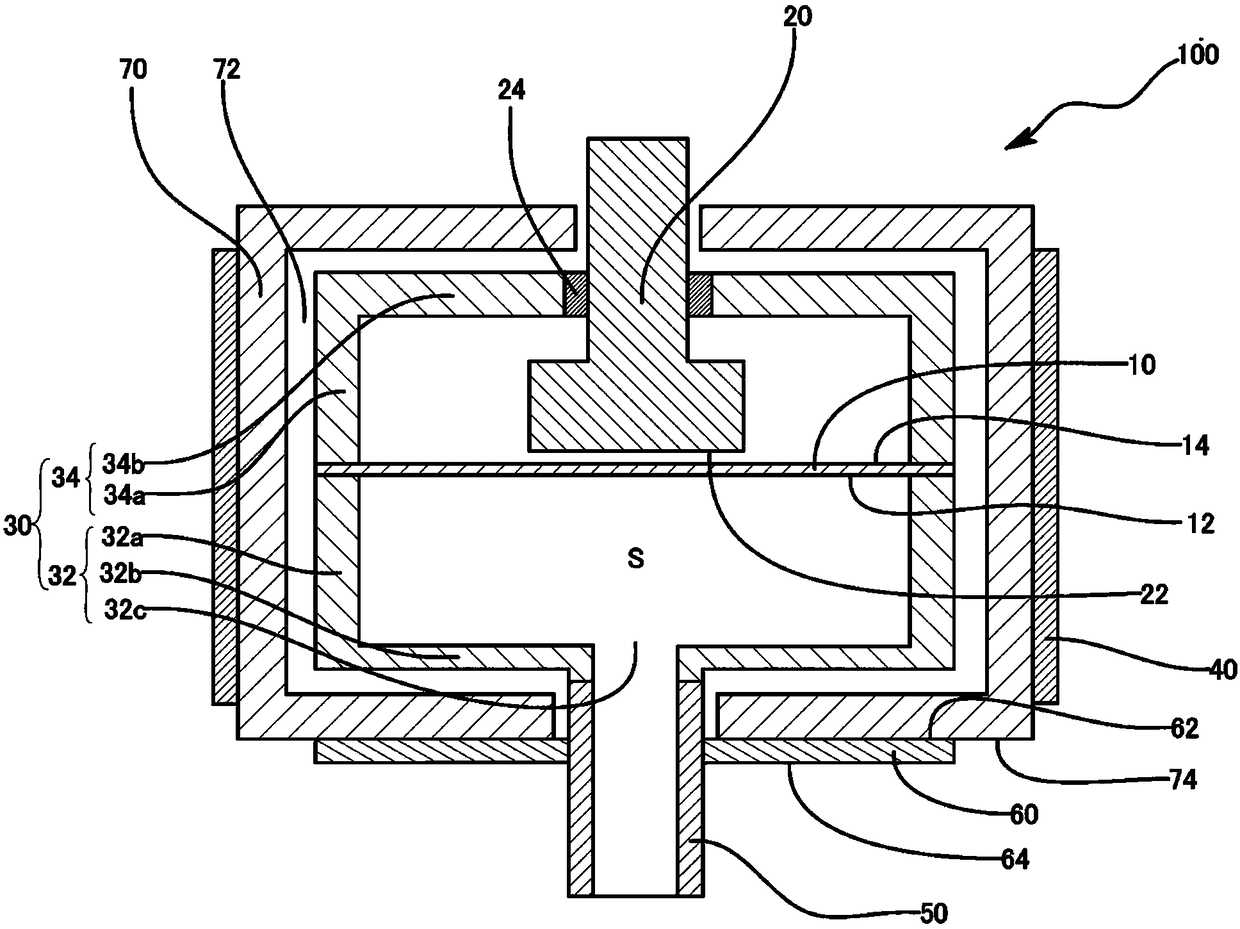
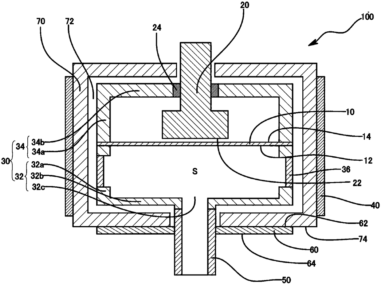
[0059] Hereinafter, an embodiment of the pressure sensor of the present invention will be described with reference to the drawings. However, the pressure sensor described below is merely an embodiment for embodying the technical idea of ​​the present invention, and the present invention is not limited to the following description unless otherwise specified. In addition, the contents described in one embodiment can also be applied in other embodiments. In addition, dimensions, positional relationships, and the like of members shown in the drawings are sometimes exaggerated for clarity of description.

[0060] The pressure sensor 100 of the present embodiment is an absolute pressure measuring capacitive diaphragm vacuum gauge equivalent to a total pressure vacuum gauge, and detects the amount of change in capacitance between the diaphragm 10 and the fixed electrode (electrode body) 20 that is displaced by pressure, and converts it to The amount of change is converted into press...


PUM


Abstract

The present invention provides a pressure sensor capable of suppressing bending of a diaphragm caused by a sudden temperature change of a fluid introduction tube provided on a fluid conduit. The pressure sensor comprises the diaphragm, an electrode body, a housing, an inlet pipe, and a thermal buffer member. The diaphragm includes a pressure receiving surface configured to receive a pressure of ameasured target fluid. The electrode body includes an electrode surface facing a rear surface of the pressure receiving surface with a gap interposed therebetween. The housing supports the diaphragm so as to form a measuring chamber by surrounding the pressure receiving surface. The inlet pipe is coupled to the housing and configured to guide the measured target fluid into the measuring chamber. The thermal buffer member is disposed on the inlet pipe and has a predetermined heat capacity.

Description

technical field [0001] The present invention relates to a pressure sensor for measuring the pressure of a fluid from a change in capacitance between a diaphragm deformed by pressure and an electrode body. Background technique [0002] Conventionally, a pressure sensor has been used in order to measure the pressure in a vacuum state in a thin film forming process in a semiconductor manufacturing process or the like. As such a pressure sensor, for example, as in Patent Document 1 and Figure 4 As shown, it includes: a housing 11, which has an introduction portion of the fluid to be measured; a diaphragm 32, which is bent under the pressure of the fluid to be measured guided through the introduction portion 10A of the housing 11; and a sensor chip 30, the diaphragm 32 changes are derived as changes in capacitance. The fluid to be measured, such as gas, flowing through the fluid pipe is taken into the inside of the case 11 by connecting the fluid introduction pipe provided on t...

Claims


Application Information

Patent Timeline
Patent Type & Authority Applications(China)
IPC IPC(8): G01L9/00
CPCG01L9/0072G01L19/147G01L19/0627G01L9/12G01L19/14
Inventor 岸田创太郎中井淳也畑板刚久桒原朗
Owner HORIBA STEC CO LTD
Why Eureka
Try Eureka