Yarn unwinding device for spinning

A wire take-up device and yarn technology, which is applied in the direction of transportation and packaging, delivery of filamentous materials, thin material processing, etc., can solve the problem of inability to realize the wire take-up work of the wire take-up drum, affect the wire take-up speed of the wire take-up device, and the wire take-up Problems such as low degree of automation of the device can achieve the effect of increasing the scope of use, increasing the degree of aesthetics, and improving the degree of automation

Inactive Publication Date: 2018-10-23
XIANGSHUI COUNTY XINHONG TEXTILE CO LTD
View PDF0 Cites 4 Cited by
  • Summary
  • Abstract
  • Description
  • Claims
  • Application Information

AI Technical Summary

Problems solved by technology

[0002] A loom twists many plant fibers together and spins them into threads or yarns that can be used to weave cloth. All spinning looms do two things. Pull out the cotton thread little by little, twist it into a fine cotton thread, and the cotton thread will become longer after twisting. After the yarn is formed, in order to facilitate storage, the yarn will be wound on a reel for storage or transportation. Existing Most of the wire take-up devices drive the reel through the motor to take up the wire through the guide wheel. This type of wire take-up is likely to cause uneven distribution of the yarn on the reel, requiring workers to adjust, and the degree of automation of the wire take-up device is low. Thereby greatly affecting the take-up speed of the take-up device, and some take-up devices cannot realize the take-up work of different take-up barrels during use, which brings great troubles to people's use

Method used


Image

  • Yarn unwinding device for spinning
  • Yarn unwinding device for spinning

Examples


Embodiment Construction

[0013] The following will clearly and completely describe the technical solutions in the embodiments of the present invention with reference to the accompanying drawings in the embodiments of the present invention. Obviously, the described embodiments are only some, not all, embodiments of the present invention. Based on the embodiments of the present invention, all other embodiments obtained by persons of ordinary skill in the art without making creative efforts belong to the protection scope of the present invention.

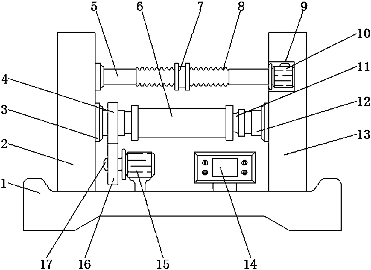
[0014] see Figure 1-2 , an embodiment provided by the present invention: a yarn take-up device for textiles, comprising a device base 1, a first vertical plate 2, a flange 3, a control panel 14 and a motor 15, one side of the top of the device base 1 A first vertical plate 2 is fixed, a second vertical plate 13 is installed on the end of the device base 1 away from the first vertical plate 2, and a flange 3 is fixed on the inner side wall of the second vertic...


PUM


Abstract

The invention discloses a yarn unwinding device for spinning. The yarn unwinding device for spinning comprises a device base, a first vertical plate, flange discs, a control panel and a motor. The first vertical plate is fixed to one side of the top end of the device base, a second vertical plate is installed at the end, away from the first vertical plate, of the device base, and the flange discsare fixed to the inner side walls of the second vertical plate and the first vertical plate. Electric telescopic columns are hinged to the outer side walls of the flange discs, a first gear is installed on the surface of the electric telescopic columns at the position of the first vertical plate through a bearing, a motor is installed at the top end of the device base below the first gear througha supporting column, rotating rollers are hinged to the inner side walls of the first vertical plate and the second vertical plate and located above a unwinding barrel, and a servo motor is fixed to the central position in a motor cavity. The yarn unwinding device for spinning improves the wire unwinding rate of the yarn unwinding device, improves the operating range of the yarn unwinding device,and improves the evenness of the unwinding device during taking-up.

Description

technical field [0001] The invention relates to the technical field of textile equipment, in particular to a yarn take-up device for textile. Background technique [0002] A loom twists many plant fibers together and spins them into threads or yarns that can be used to weave cloth. All spinning looms do two things. Pull out the cotton thread little by little, twist it into a fine cotton thread, and the cotton thread will become longer after twisting. After the yarn is formed, in order to facilitate storage, the yarn will be wound on a reel for storage or transportation. Existing Most of the wire take-up devices drive the reel through the motor to take up the wire through the guide wheel. This kind of wire take-up method is likely to cause uneven distribution of the yarn on the reel, requiring workers to adjust, and the degree of automation of the wire take-up device is low. Thereby greatly affecting the take-up speed of the take-up device, and some take-up devices can't rea...

Claims


Application Information

Patent Timeline
Patent Type & Authority Applications(China)
IPC IPC(8): B65H54/28B65H54/54B65H54/74
CPCB65H54/2818B65H54/54B65H54/74B65H2403/92B65H2701/31
Inventor 夏学东夏子昂
Owner XIANGSHUI COUNTY XINHONG TEXTILE CO LTD
Why Eureka
Try Eureka