Gas control system of reflow oven and method of the same

A control system and reflow furnace technology, applied in manufacturing tools, auxiliary devices, metal processing equipment, etc., can solve problems such as incompleteness, wasteful replacement of inert gas, affecting ventilation effect, etc., to save power, reduce waste, and avoid impact. Worker health effects

Active Publication Date: 2018-10-19
武汉倍普科技有限公司
View PDF8 Cites 0 Cited by
  • Summary
  • Abstract
  • Description
  • Claims
  • Application Information

AI Technical Summary

Problems solved by technology

[0005] Aiming at the deficiencies of the prior art, the present invention provides a reflow furnace gas control system and method, which solves the problem of completely replacing the internal oxygen with an inert gas at a specified time through the cooperation of the two devices, but if the cooperation of the two devices If it is not synchronized, it will affect the ventilation effect, which may cause the waste of inert gas or the problem of incomplete replacement

Method used


Image

  • Gas control system of reflow oven and method of the same
  • Gas control system of reflow oven and method of the same
  • Gas control system of reflow oven and method of the same

Examples


Embodiment Construction

[0033] The following will clearly and completely describe the technical solutions in the embodiments of the present invention with reference to the accompanying drawings in the embodiments of the present invention. Obviously, the described embodiments are only some of the embodiments of the present invention, not all of them. Based on the embodiments of the present invention, all other embodiments obtained by persons of ordinary skill in the art without making creative efforts belong to the protection scope of the present invention.

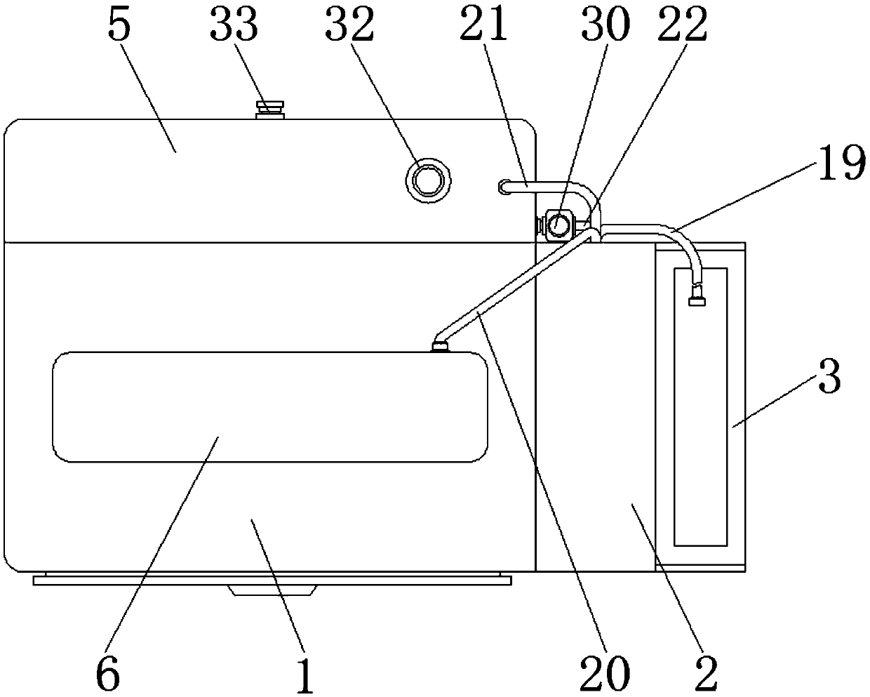
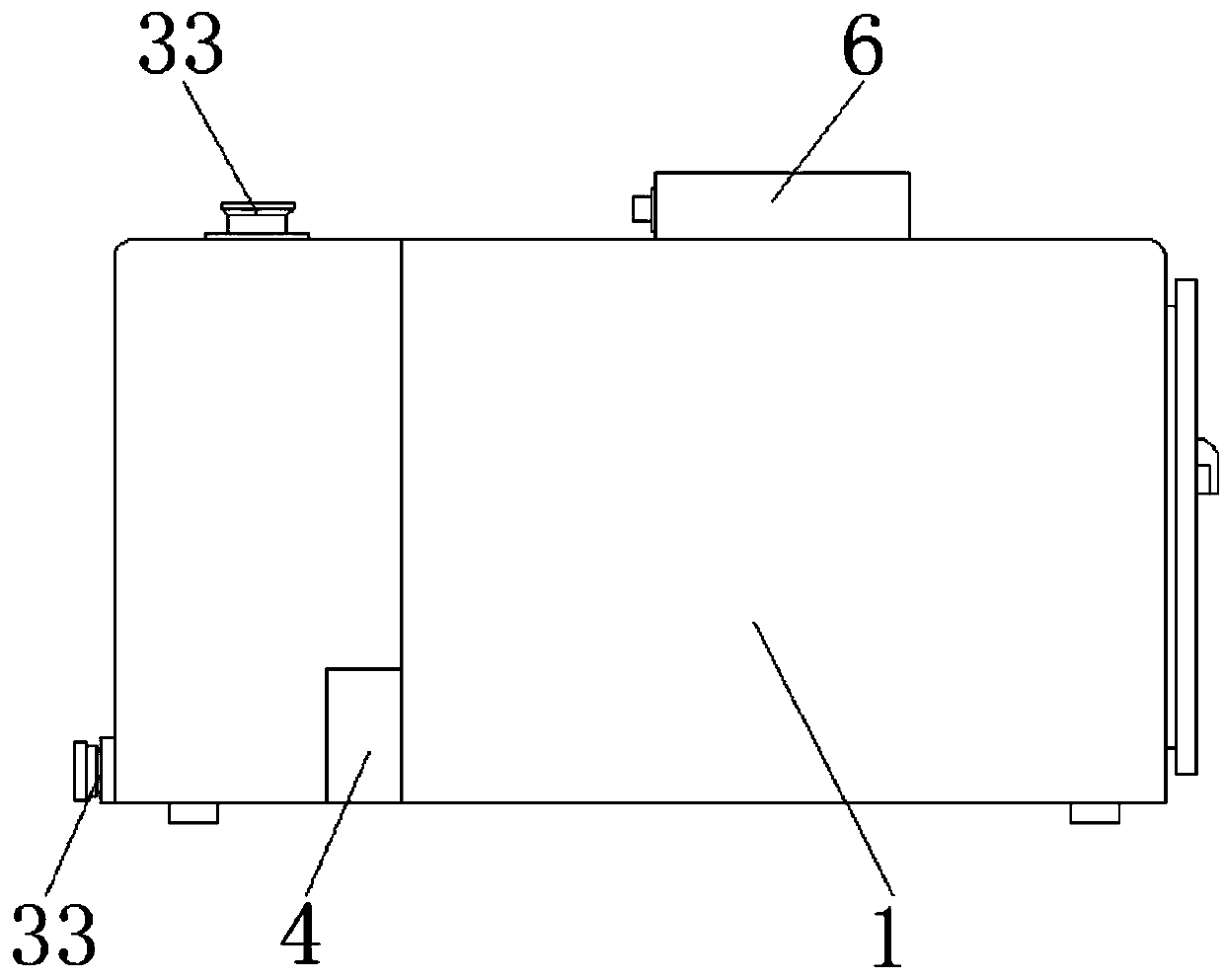
[0034] see Figure 1-5 , the embodiment of the present invention provides a technical solution: a reflow furnace gas control system, including a reflow furnace body 1, the right side of the reflow furnace body 1 is fixedly connected with an organic case 2, and the bottom of the right side of the case 2 is fixedly connected with a tray 3 , the tray 3 is used to place the helium tank, the bottom of the inner cavity of the chassis 2 and the back of ...


PUM


Abstract

The invention discloses a gas control system of a reflow oven and a method of the same. The system comprises a reflow oven body, the right side of the reflow oven body is fixedly connected with a machine box, and the bottom of the right side of the machine box is fixedly connected with a tray; and the bottom of the back side of the reflow oven body communicates with an air suction box, a water tank is fixedly connected between the back face of the reflow oven body and the top of the air suction box; and the invention relates to the technical field of reflow ovens. According to the gas controlsystem of the reflow furnace and the method of the same, through the movement of a crankshaft, and two push rods can push a piston to move in turn through the cooperation of a fixing sleeve and a rotating rod, through the cooperation among four pipelines and four one-way valves, air in the reflow oven body can be replaced with helium gas before machining, so that oxygen can be prevented from affecting machining, air sucking and exhausting can be carried out at the same time, and the working efficiency is high; and the internal waste gas can be pumped out after the machining, use is convenientthrough a device to realized, moreover, the air sucking and the exhausting can be carried out synchronously, so that the gas exchange can be guaranteed thoroughly.

Description

technical field [0001] The invention relates to the technical field of reflow furnaces, in particular to a gas control system and method for reflow furnaces. Background technique [0002] The reflow oven, also known as the reflow oven (also called reflow soldering, reflow oven, reflow oven), is a kind of equipment required by the SMT process of the electronic technology industry. The reflow oven process is to achieve the soldering of the mechanical and electrical connections between the surface mount component terminals or pins and the printed board pads by remelting the paste solder that is pre-distributed on the printed board pads . The reflow furnace is the last key process of SMT. It is a real-time process control. Its process changes are complicated and involve many process parameters. Among them, the setting of the temperature curve is the most important, which directly determines the quality of reflow soldering. The temperature curve of the reflow oven is divided in...

Claims


Application Information

Patent Timeline
Patent Type & Authority Applications(China)
IPC IPC(8): B23K3/08B23K1/008
CPCB23K1/008B23K3/08
Inventor 丁凡
Owner 武汉倍普科技有限公司
Why Eureka
Try Eureka