
Electrostatic dust collector used for preform rod extending technology

An electrostatic precipitator and preformed rod technology, applied in the field of electrostatic precipitators, can solve problems such as unstable quality, and achieve the effects of reducing production costs, increasing cleanliness and long service life

Pending Publication Date: 2018-10-19
JIANGSU STERLITE TONGGUANG FIBER
View PDF18 Cites 0 Cited by
  • Summary
  • Abstract
  • Description
  • Claims
  • Application Information

AI Technical Summary

Problems solved by technology

[0006] In order to overcome the problem of unstable quality caused by soot cavitation of the preform in the extension process existing in the prior art, the present invention provides an electrostatic precipitator in the preform extension process, which can The dust removal device can make the surface of the extended light rod smooth and free of impurities, which greatly improves the quality of the extended light rod surface

Method used


Image

  • Electrostatic dust collector used for preform rod extending technology
  • Electrostatic dust collector used for preform rod extending technology
  • Electrostatic dust collector used for preform rod extending technology

Examples


Embodiment 1

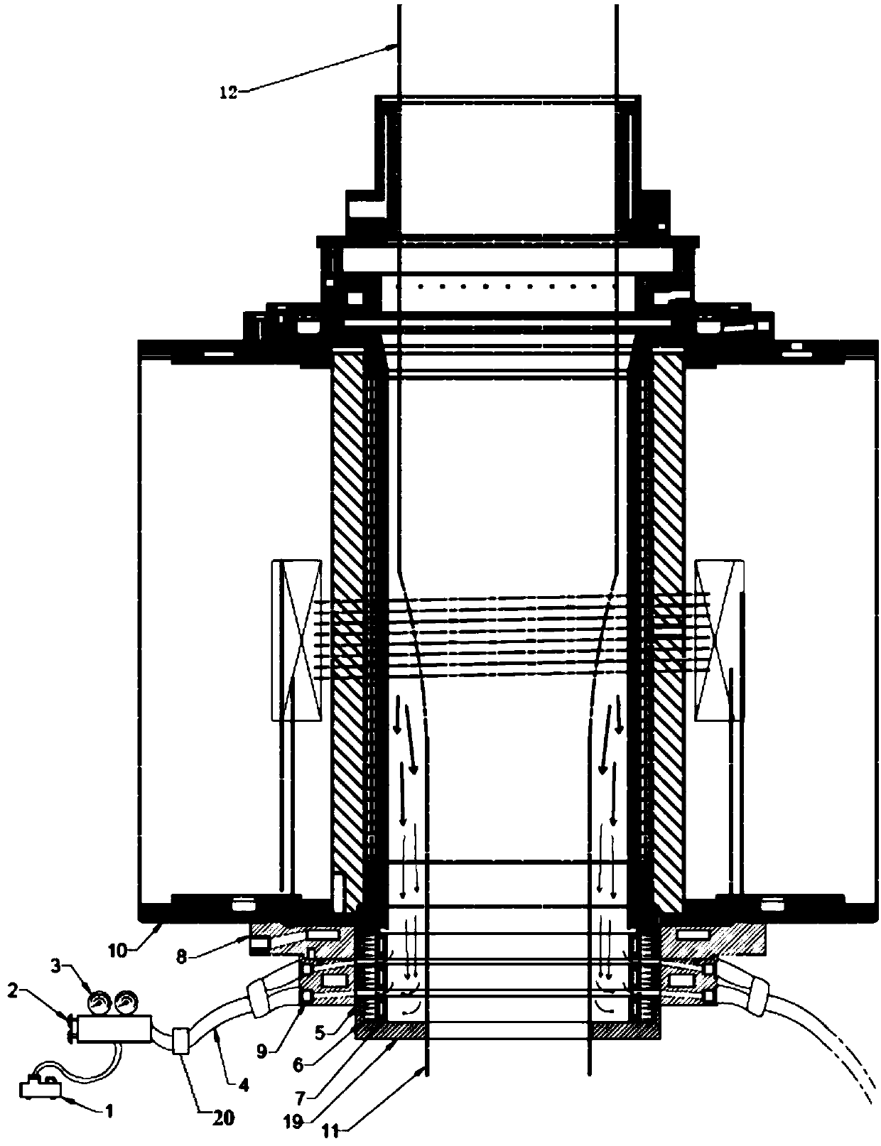
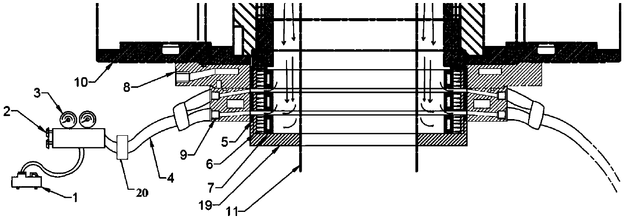
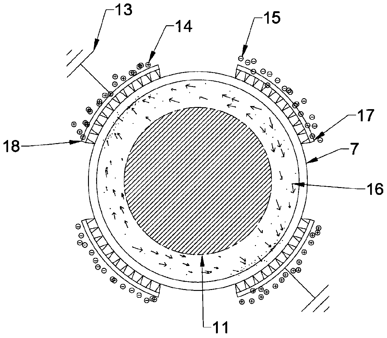
[0030] Such as figure 1 , figure 2 As shown, an electrostatic precipitator in the preform extension process, wherein the electrostatic precipitator is located at the outlet below the extension furnace 10, and the electrostatic precipitator has a first water-cooled plate 8 and a second water-cooled plate 9 outside; the electrostatic precipitator includes an electrostatic precipitator Field generating device and exhaust device, the electrostatic field generating device includes an electrode water cooling plate 7, an electrostatic field electrode plate 6, and an insulating component 5 arranged in sequence from the inside to the outside; Externally, the insulating part 5 is located between the electrostatic field plate 6 and the first water-cooled plate 8 and the second water-cooled plate 9; the exhaust device includes an exhaust pump 1, a control valve 2, a pressure gauge 3, an exhaust pipe 4 connected in sequence, and exhaust The air outlet of the gas pipeline 4 communicates w...

Embodiment 2

[0041] Such as figure 1 , figure 2 As shown, an electrostatic precipitator in the preform extension process, wherein the electrostatic precipitator is located at the outlet below the extension furnace 10, and the electrostatic precipitator has a first water-cooled plate 8 and a second water-cooled plate 9 outside; the electrostatic precipitator includes an electrostatic precipitator Field generating device and exhaust device, the electrostatic field generating device includes an electrode water cooling plate 7, an electrostatic field electrode plate 6, and an insulating component 5 arranged in sequence from the inside to the outside; Externally, the insulating part 5 is located between the electrostatic field plate 6, the first water cooling plate 8, and the second water cooling plate 9; The air outlet of the gas pipeline 4 communicates with the exhaust pump 1 , and the air inlet of the exhaust pipeline 4 communicates with the air hole on the electrode water cooling plate 7 ...


PUM


Abstract

The invention provides an electrostatic dust collector used for a preform rod extending technology. The electrostatic dust collector is characterized in that the electrostatic dust collector is located in an outlet formed in the lower portion of an extending furnace, and a first water cooling plate and a second water cooling plate are arranged outside the electrostatic dust collector; the electrostatic dust collector comprises an electrostatic field generating device and a gas exhausting device, and the electrostatic field generating device comprises an electrode water cooling plate, an electrostatic field polar plate and an insulating component which are distributed from inside to outside in sequence; and the gas exhausting device comprises an exhaust pump, control valves, pressure gagesand a gas exhausting pipeline which are connected in sequence, a gas outlet of the gas exhausting pipeline communicates with the exhaust pump, and a gas suction inlet of the gas exhausting pipeline communicates with air holes in the electrode water cooling plate. According to the electrostatic dust collector used for the preform rod extending technology, the purpose that the interior of the furnace is clean can be achieved, the practice that the lower furnace outlet is expanded to improve the cleanliness of the surface of an optical rod is not needed, a heater can be made to have a longer service life, and the production cost is lowered.

Description

technical field [0001] The invention relates to the technical field of optical fiber optical rod sheathing extension technology, in particular to an electrostatic precipitator in the preform rod extension technology. Background technique [0002] In the field of optical fiber, the RIC process alleviates the bottleneck production capacity problem in the domestic direct outsourcing process of preform rod preparation, and avoids the core rod retention problem caused by direct outsourcing technology investment and insufficient production capacity. In the RIC process, the mandrel is directly reassembled with the casing. This method can further integrate the deposited sheath and the mandrel to form optical rods with various outer diameters to facilitate wire drawing. However, there are still some shortcomings in the light rods extended by this method, that is, the surface is white and foggy, and there is soot deposition. Even if there is an improved method, the life of the extende...

Claims


Application Information

Patent Timeline
Patent Type & Authority Applications(China)
IPC IPC(8): B03C3/08B03C3/40B03C3/68B03C3/70B03C3/34
CPCB03C3/08B03C3/34B03C3/40B03C3/68B03C3/70
Inventor 张荣旺孙建彬巴拉及维捷王安亮王谦陈小龙杨梅
Owner JIANGSU STERLITE TONGGUANG FIBER
Learn More