
Locking coupling

A technology of couplings and components, applied in the direction of couplings, mechanical equipment, etc., can solve problems such as loosening of fixed parts, and achieve the effect of avoiding leakage

Active Publication Date: 2014-06-18
VIVONIC GMBH
View PDF5 Cites 0 Cited by
  • Summary
  • Abstract
  • Description
  • Claims
  • Application Information

AI Technical Summary

Problems solved by technology

[0005] But even in the case of material combinations, the coupling halves, or their immobile fixing parts, can still loosen

Method used


Image

  • Locking coupling
  • Locking coupling
  • Locking coupling

Examples


Embodiment Construction

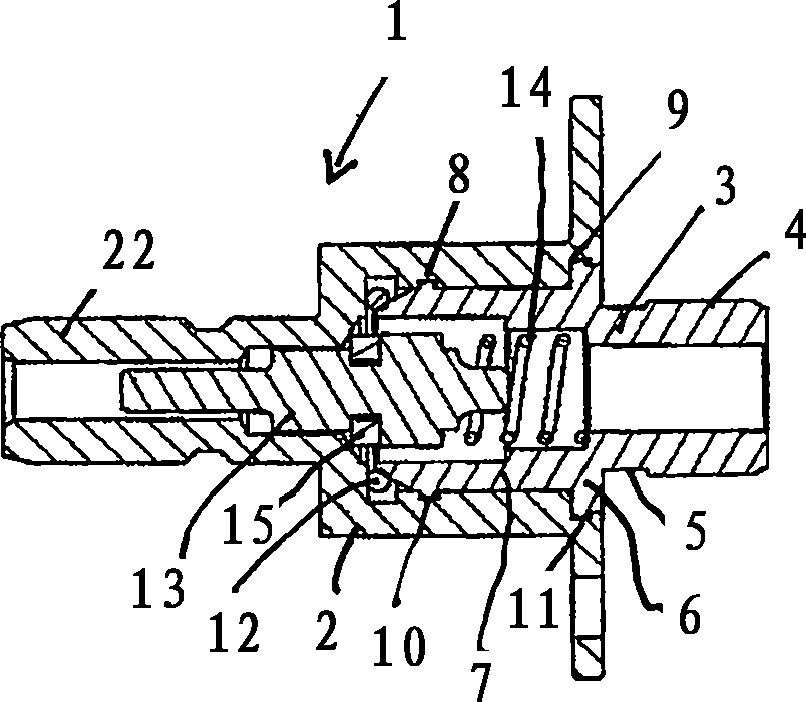
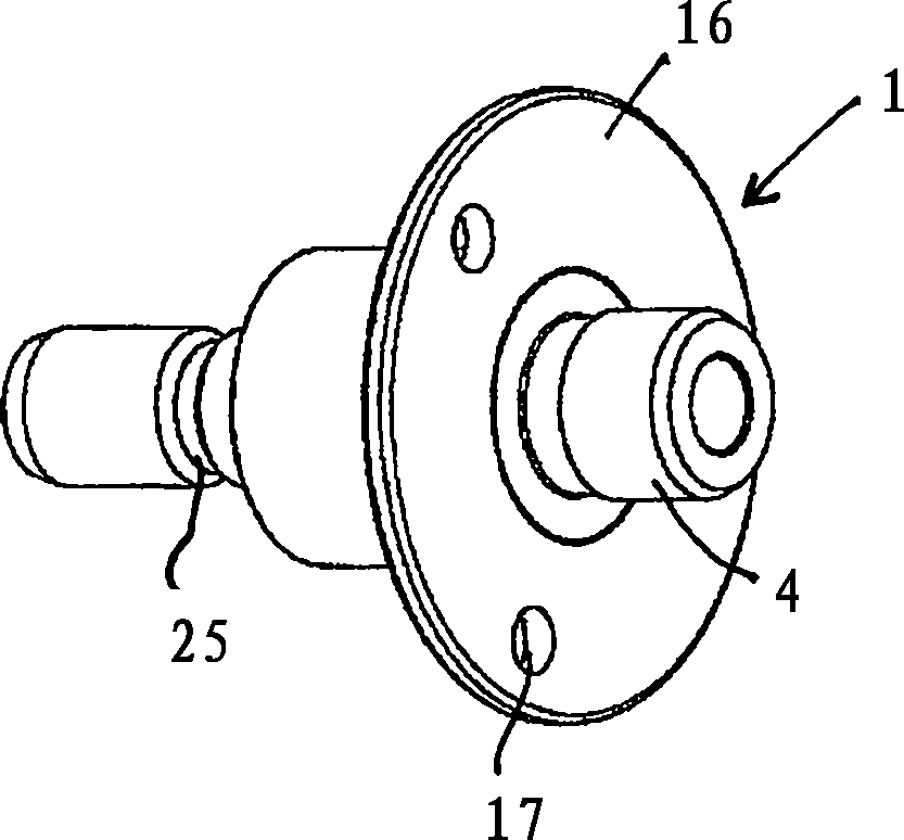
[0027] exist Figure 1a and 1b The nipple parts shown in are generally designated with the reference number 1 . It is composed of a nipple element 2 and a closure 3 which is inserted into the nipple element 2 . On its free end section, the closure element 3 comprises a threaded section 4 or else a smooth cylinder which merges behind the constriction 5 into the flange-like projection 6 . This is followed by a segment with a smooth cylindrical peripheral surface, which has an outer annular bead 8 near its free end. Flange 6 likewise includes an annular projection 9 on its outer circumference.

[0028] Figure 1a and 1b The locked state of the locking element 3 into the nipple element 2 is shown. For this purpose, annular grooves 10 and 11 are formed at corresponding positions on the inner surface of the inner connection element 2 , into which annular projections 8 and 9 snap into place elastically. It is to be understood here that the locking element 3 and the connector ele...


PUM


Abstract

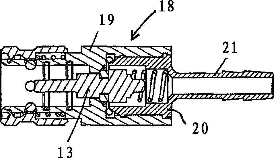
The coupling unit comprises a fitting part (1) and a coupling part (18) and is characterized in that the fitting part (1) and / or the coupling part (18) are composed of a locking piece (3, 20), which at one end section has a section (4) for fastening in a pipe socket of the pipe or in the stationary unit and at the other end has detent elements (8, 9), and a fitting element (2) or a coupling element (19), the locking piece (3, 20) being inserted into said fitting or coupling element, and detent elements (8, 9, 10, 11) are configured on the locking piece (3, 20) and the fitting element (2) or coupling element (19), wherein said detent elements in the fully inserted state of the locking piece (3, 20) into the fitting element (2) or coupling element (19) engage in each other  and fix the axial cohesion of the two parts. In this way, it is ensured that the connection between the locking piece (3, 20) and the coupling element (19) or fitting element (2) cannot loosen over time as a result of the frequent connecting and disconnecting of the coupling unit, thereby preventing leakages in the region of the coupling unit.

Description

technical field [0001] The invention relates to a coupling unit, comprising a nipple part and a coupling part, for diverting liquid from a pipe or a fixed unit or for delivering or extracting a liquid from a flexible hose connection to a pipe or a fixed unit Structural arrangement in a unit in which one part of the coupling unit is fixed in a section in a pipe or in a fixed unit, and a spring-preloaded to latch is movably supported in the inner joint part and in the coupling part, respectively. valve body in position. Background technique [0002] Couplings made of metal or a combination of metal and plastic are known. [0003] In the couplings of the type concerned, not only the inner joint part but also the coupling part are made of two parts, one for inserting the sealing valve and the other for accommodating different connection joints, e.g. Screw-in thread or hose connection for flexible transfer lines. [0004] Due to the rheological properties and the softness of p...

Claims


Application Information

Patent Timeline
Patent Type & Authority Patents(China)
IPC IPC(8): F16L37/36
CPCF16L37/34F16L37/23
Inventor 曼弗雷德·弗尔克尔
Owner VIVONIC GMBH
Learn More