
Multistage axial flow compressor with inter-static-blade self-circulating gas suction and injection functions

An axial flow compressor and self-circulation technology, which is applied in axial flow pumps, mechanical equipment, machines/engines, etc., can solve the problems affecting the efficiency and economy of the whole machine, and achieve the reduction of total loss, improvement of efficiency, and airflow angle of attack increased effect

Inactive Publication Date: 2018-10-16
INST OF ENGINEERING THERMOPHYSICS - CHINESE ACAD OF SCI
View PDF7 Cites 5 Cited by
  • Summary
  • Abstract
  • Description
  • Claims
  • Application Information

AI Technical Summary

Problems solved by technology

The research also shows that the application of boundary layer suction technology alone will discharge part of the fluid that has been powered, which will affect the efficiency and economy of the whole machine

Method used


Image

  • Multistage axial flow compressor with inter-static-blade self-circulating gas suction and injection functions
  • Multistage axial flow compressor with inter-static-blade self-circulating gas suction and injection functions
  • Multistage axial flow compressor with inter-static-blade self-circulating gas suction and injection functions

Examples


Embodiment Construction

[0036] In the process of realizing the present invention, the applicant found that: using the boundary layer suction technology alone will affect the degree of improvement of the efficiency of the whole machine due to the part of the high-pressure fluid being drawn away from the compressor; and the boundary layer air injection technology needs to start from External air source or high-pressure level bleed air, the separate application of the two technologies requires complex auxiliary devices, and the cost of implementation is relatively high.

[0037] The applicant creatively combined the above two technologies to provide a multi-stage axial flow compressor. The multi-stage axial flow compressor is provided with a self-circulating pump between the suction surface of the high-pressure stage vane and the suction surface of the low-pressure stage vane. The suction jet device uses the static pressure difference between the high-pressure stage and the low-pressure stage in the mult...


PUM


Abstract

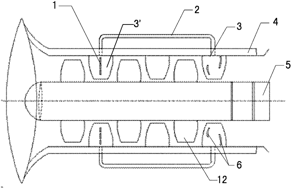
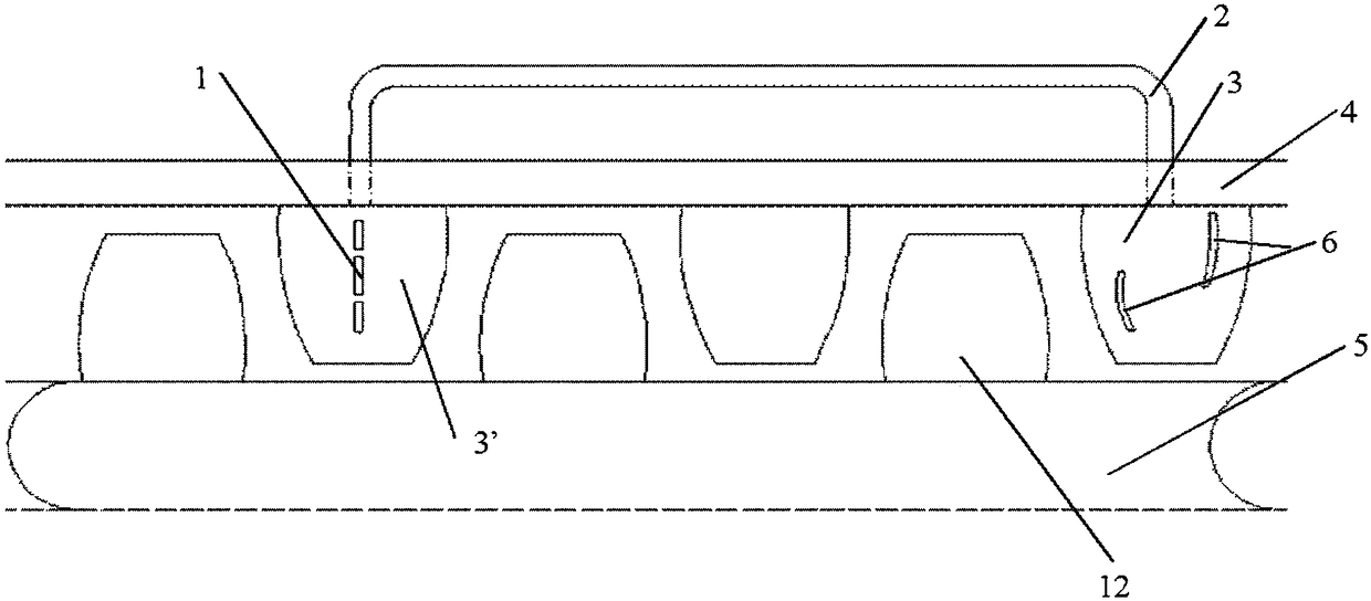
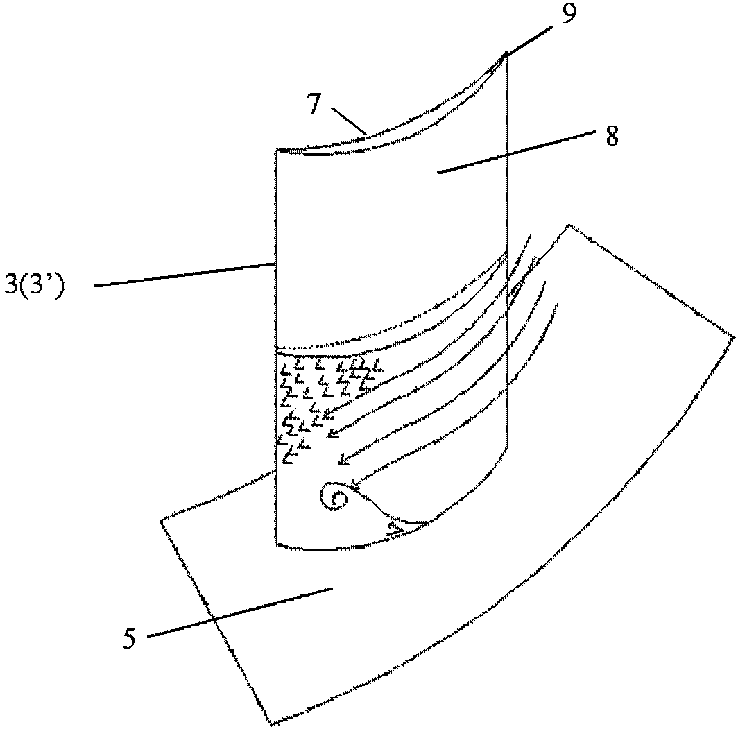
The invention provides a multistage axial flow compressor with the inter-static-blade self-circulating gas suction and injection functions. The multistage axial flow compressor comprises a casing, a hub, N rows of static blades, a self-circulating gas suction and injection device and M rows of movable blades, wherein the hub is arranged at the center axis position of the casing, the N rows of static blades are arranged on the inner side of the casing in the axial direction of the casing, the self-circulating gas suction and injection device is arranged between one high-pressure-stage static blade and another low-pressure-stage static blade of the N rows of static blades, the M rows of movable blades are arranged on the outer side of the hub in the axial direction of the casing, the movableblades and the static blades are arranged in a staggered mode, N is greater than or equal to 2, M is greater than or equal to 1, and the self-circulating gas suction and injection device guides gas on suction surfaces of the high-pressure-stage static blades guided back to suction surfaces of the low-pressure-stage static blades for boundary-layer gas injection by utilizing the static pressure difference between the high-pressure stage and the low-pressure stage in the multistage axial flow compressor. According to the multistage axial flow compressor, the beneficial effects of boundary-layergas suction and injection technologies can both be achieved, so that the dual purposes of improving the stability margin and improving the efficiency can be achieved.

Description

technical field [0001] The invention relates to the technical field of gas turbines / aeroengines, in particular to a multi-stage axial flow compressor capable of self-circulating suction jets between vanes. Background technique [0002] As one of the key components of gas turbine / aeroengine, the compressor is currently developing towards high load and high stability. Increasing the load will make the internal flow of the compressor very complicated. For the stator blade, the strong reverse pressure gradient will intensify the flow separation of the boundary layer on the suction surface and increase the blade shape loss. In addition, the unsteady rotation-static interference will generate a lot of noise, and the pressure loss in the flow field at the outlet of the upstream vane will aggravate the unsteadiness and non-uniformity of the downstream rotor inlet, which may cause high-cycle fatigue of the engine and affect the performance of the engine. service life. Therefore, it...

Claims


Application Information

Patent Timeline
IPC IPC(8): F04D29/54F04D29/66F04D19/02
CPCF04D29/542F04D19/02F04D29/667
Inventor 杜娟李艺雯李继超李志远张宏武
Owner INST OF ENGINEERING THERMOPHYSICS - CHINESE ACAD OF SCI
Learn More