A balance sink structure for eliminating the hydraulic power of the cartridge valve core

A technology of hydraulic power and cartridge valve, applied in valve details, valve device, sliding valve, etc., can solve the problems of poppet valve spool prone to vibration, hydraulic system damage, hydraulic system pressure fluctuation, etc., to eliminate the cartridge valve hydrodynamic effect

Active Publication Date: 2019-06-18
ZHEJIANG UNIV
View PDF6 Cites 0 Cited by
  • Summary
  • Abstract
  • Description
  • Claims
  • Application Information

AI Technical Summary

Problems solved by technology

[0003] However, in practical applications, the poppet valve core is prone to vibration
Vibration induces noise, and its poor stability causes pressure fluctuations in the hydraulic system, which brings great harm to the entire hydraulic system

Method used


Image

  • A balance sink structure for eliminating the hydraulic power of the cartridge valve core
  • A balance sink structure for eliminating the hydraulic power of the cartridge valve core
  • A balance sink structure for eliminating the hydraulic power of the cartridge valve core

Examples


Embodiment 1

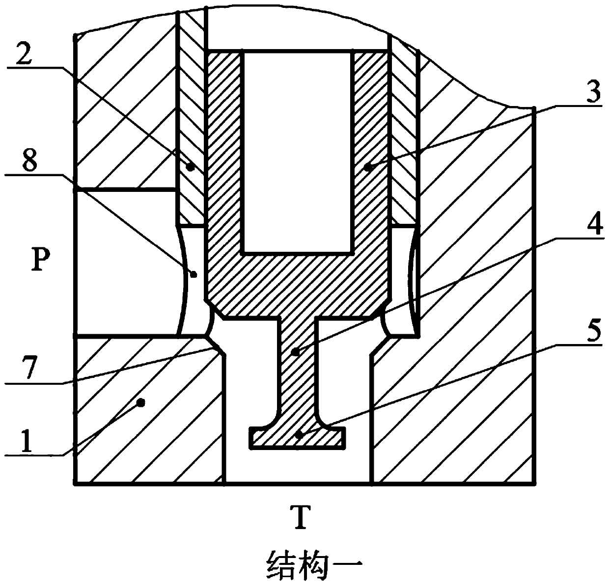
[0025] The first structure is a cartridge valve, such as figure 1 As shown, it includes a valve body 1, a valve sleeve 2, a valve core 3, a connecting rod 4 and a balance pendant 5.

[0026] In structure one, there is a chamfer 7 inside the valve body 1, and the valve body 1 has two oil ports, which are the oil inlet P and the oil return port T; the valve sleeve 2 is installed inside the valve body, and the valve sleeve is evenly distributed in the circumferential direction The four throttle holes 8 and the valve core 3 are installed in the cylindrical hole inside the valve sleeve to form a sliding fit. The balance pendant 5 is connected with the valve core 3 through the connecting rod 4 as a whole.

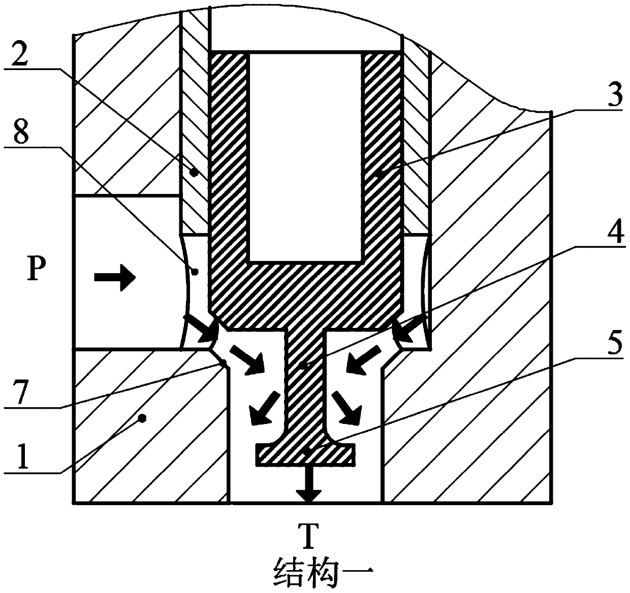
[0027] The present invention eliminates the working principle of cartridge valve spool hydraulic power as follows:

[0028] The working principle of structure one is as follows image 3 As shown, the spool 3 moves upward to open the oil passage groove, so that the hydraulic oil...

Embodiment 2

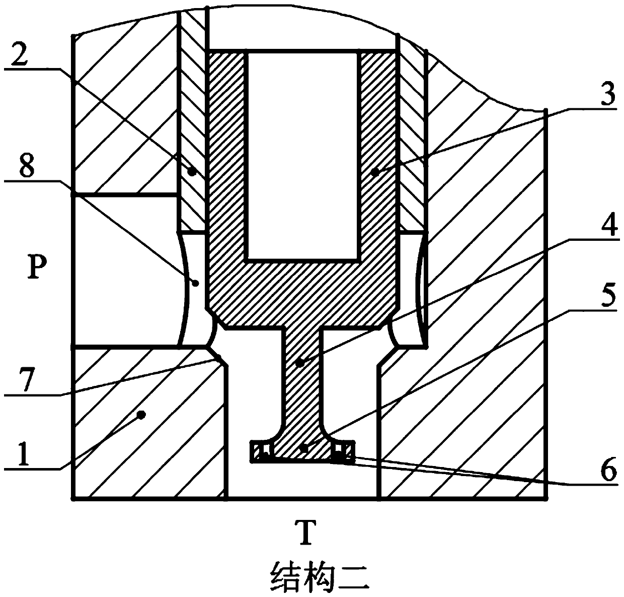
[0034] The second structure is a cartridge valve, such as figure 2 As shown, it includes valve body 1, valve sleeve 2, valve core 3, connecting rod 4, balance pendant 5 and diversion hole 6.

[0035] In structure 2, there is a chamfer 7 inside the valve body 1, and the valve body 1 has two oil ports, which are the oil inlet P and the oil return port T; the valve sleeve 2 is installed inside the valve body, and the valve sleeve is evenly distributed in the circumferential direction Four throttle holes 8, the valve core 3 are installed in the cylindrical hole inside the valve sleeve to form a sliding fit, and the balance pendant 5 is connected with the valve core 3 through the connecting rod 4 as a whole; the diversion hole 6 is located on the balance pendant 5, Evenly distributed in the circumferential direction, forming a balance pendant with holes.

[0036] The working principle of structure two is as follows Figure 4 As shown, the spool 3 moves upward to open the oil pas...


PUM


Abstract

The invention discloses a balance weight structure for eliminating fluid power on a valve element of a cartridge valve. The balance weight structure comprises a valve, a valve sleeve and the valve element. Chamfer angles are arranged at the inner edges of the inner end surfaces of oil return openings of the valve and are matched with cone angles of the outer edges of the end surfaces of the valve element, the balance weight is connected with the center of the bottom of the valve element, is connected to the centers of the end surfaces, which are close to the oil return openings, of the valve element by a connecting rod and is integrally connected with the valve element by the connecting rod, and the balance weight and the valve element are arranged in the same axial direction; a plurality of flow guide holes are formed in the balance weight and are peripherally uniformly formed in the outer edge of the end surface of a large end of the balance weight, and the axes of the various flow guide holes are parallel to the axis of the balance weight. The balance weight structure has the advantages that the fluid power on the two-way cartridge valve can be eliminated, the elimination degree of the fluid power on the valve element can be regulated, and accordingly the elimination degree of the fluid power on the valve element of the cartridge valve can be regulated.

Description

technical field [0001] The invention relates to a balance pendant structure for eliminating hydrodynamic power of a valve core of a hydraulic valve, in particular to a balance pendant structure for eliminating hydrodynamic power of a cartridge valve core. Background technique [0002] Cartridge valves are widely used in various hydraulic control systems because of their simple structure, large flow rate and fast action speed. Due to the large contact stress between the poppet valve core and the valve seat, good sealing performance and high sensitivity, it is widely used in ordinary hydraulic valves, so the cartridge valve mostly uses the poppet valve core as its valve core. [0003] However, in practical applications, the poppet valve core is prone to vibration. Vibration induces noise, and its poor stability causes pressure fluctuations in the hydraulic system, which brings great harm to the entire hydraulic system. Contents of the invention [0004] In order to elimina...

Claims


Application Information

Patent Timeline
Patent Type & Authority Patents(China)
IPC IPC(8): F16K3/314F16K3/30F16K47/02
CPCF16K3/30F16K3/314F16K47/02
Inventor 谢海波谭礼刘建彬杨华勇
Owner ZHEJIANG UNIV
Why Eureka
Try Eureka