Method and system for determining installation position of rate gyroscope

A technology for installing position and rate gyroscopes, applied in geometric CAD, design optimization/simulation, etc., can solve the problems of long and thin structure, increase product cost, and fast change, so as to improve stability margin and reduce high attenuation Demand, the effect of reducing product costs

Active Publication Date: 2020-04-21
广州中科宇航探索技术有限公司
View PDF10 Cites 0 Cited by
  • Summary
  • Abstract
  • Description
  • Claims
  • Application Information

AI Technical Summary

Problems solved by technology

Compared with the liquid launch vehicle, the burning rate of the solid engine is relatively fast and the specific impulse is relatively low. In order to overcome the dead weight of the engine after combustion as soon as possible and improve the carrying capacity, the solid launch vehicle often adopts the design of more stages, resulting in structural The slenderness ratio is large; on the other hand, although the first-order frequency of the solid launch vehicle is relatively high, its frequency changes rapidly with time; moreover, in order to reduce the launch cost as much as possible, it is expected to use as few rate gyroscopes as possible. Suppress multi-level elastic vibration; therefore, the elastic suppression control of solid launch vehicle has its inherent characteristics, and it needs to carry out targeted design
[0003] The traditional rate gyro layout method often gives a rough installation position according to the structural layout constraints, and only gives a feasibility conclusion through comprehensive verification. It lacks a quantitative optimization design process, which makes it difficult to design notch filters and affects the margin of the control system. Causes the sacrifice of system response bandwidth and noise sensitivity; or uses independent rate gyroscopes at all levels, but this increases product cost

Method used


Image

  • Method and system for determining installation position of rate gyroscope
  • Method and system for determining installation position of rate gyroscope
  • Method and system for determining installation position of rate gyroscope

Examples


Embodiment Construction

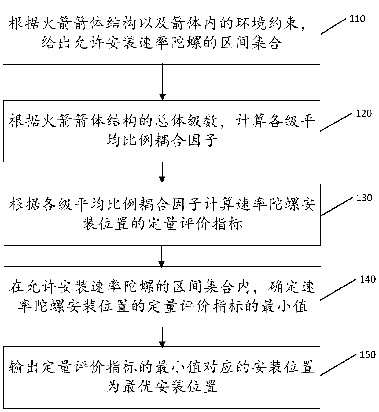
[0024] The technical solutions in the embodiments of the present application are clearly and completely described below in combination with the drawings in the embodiments of the present application. Obviously, the described embodiments are part of the embodiments of the present application, not all of them. Based on the embodiments in this application, all other embodiments obtained by those skilled in the art without making creative efforts belong to the scope of protection of this application.

[0025] The present application relates to a method and system for determining the installation position of a rate gyroscope. According to this application, the installation position of the rate gyro is optimized, the demand for high attenuation of the notch filter caused by insufficient elastic suppression control margin is reduced, and the flight stability margin, dynamic characteristics and control accuracy are improved. Use a single-rate gyro per channel to adapt to multi-level f...


PUM


Abstract

The invention discloses a method and system for determining the installation position of a rate gyroscope, and the method for determining the installation position of the rate gyroscope specifically comprises the following steps: giving an interval set allowing the installation of the rate gyroscope according to the structure of a rocket body and the environmental constraints in the rocket body; calculating an average proportional coupling factor of each stage according to the overall stage number of the rocket body structure; calculating a quantitative evaluation index of the installation position of the rate gyroscope according to the average proportional coupling factor of each level; determining the minimum value of the quantitative evaluation index of the installation position of therate gyroscope in the interval set allowing the rate gyroscope to be installed; and outputting the installation position corresponding to the minimum value of the quantitative evaluation index as theoptimal installation position. According to the invention, the high attenuation requirement of the notch filter caused by insufficient elastic suppression control margin can be reduced, and the stability margin, dynamic characteristics and control precision of flight are improved.

Description

technical field [0001] The present application relates to the field of rockets, in particular to a method and system for determining the installation position of a rate gyroscope. Background technique [0002] In order to avoid the coupling effect between the rigid body attitude control system and the elastic vibration of the structure due to the additional rotational angular velocity introduced by the elastic vibration of the structure where the inertial measurement unit (IMU) is installed in the rigid body attitude control of the launch vehicle, one or more As a separate angular velocity measuring device, the rate gyro is installed at a position where the elastic rotation range is small or can cancel each other out, so as to improve the quality of the attitude control system. If the rate gyro is still difficult to meet the control margin requirements, it is necessary to add a correction network, usually a digital filter. The frequency characteristics of the filter are notc...

Claims


Application Information

Patent Timeline
Patent Type & Authority Applications(China)
IPC IPC(8): G06F30/15G06F30/20
CPCY02T90/00
Inventor 马玉海吴炜平廉洁张霞刘凯袁春贵杨毅强
Owner 广州中科宇航探索技术有限公司
Why Eureka
Try Eureka