


Quick Research
Generate reliable direction feasibility study reports for your R&D in just a few steps.

Technical Q&A
Discover and master advanced knowledge NOW. Basics, ideas, possibilities, all at once.

Find Solutions
As an expert in R&D theories, this can generate solutions to your technical problems instantly.

Evaluate Feasibility
Analyze your overall solution with one click, know your potential R&D risks in advance.

Monitor Landscape
Get weekly tech updates, stay abreast of the latest tech innovations and key insights.
Sludge drying device
A sludge drying and sludge technology, applied in the direction of dewatering/drying/concentrating sludge treatment, can solve the problems of large steam consumption and easy sludge adhesion, and achieve the effect of slowing down the steam flow rate and reducing the amount of steam consumption.
- Summary
- Abstract
- Description
- Claims
- Application Information
AI Technical Summary
Problems solved by technology
Method used
Image

Examples
Embodiment 1
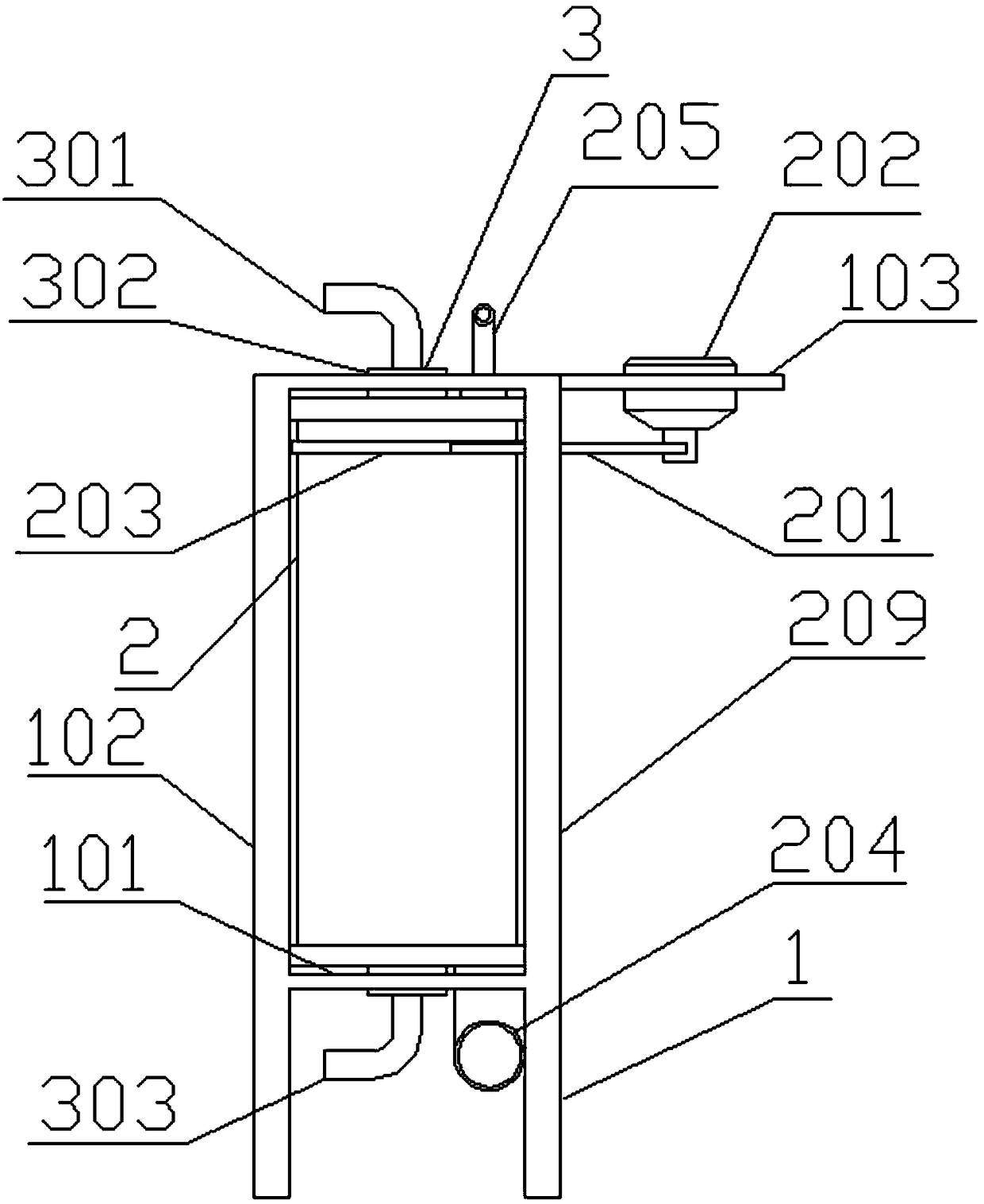
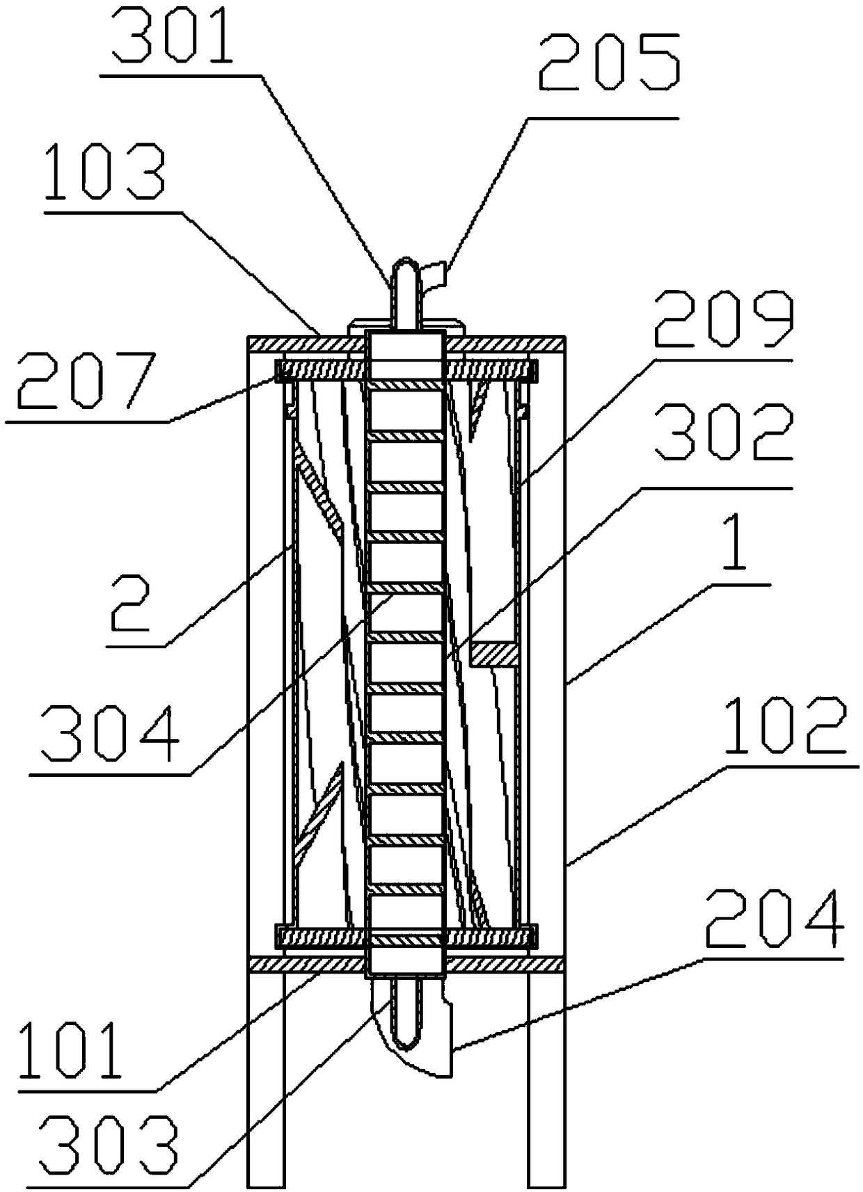
[0031] Such as Figure 1-7 Shown: a sludge drying device, including a frame system 1, a heating system 3 and a stirring system 2, the frame system 1 includes a lower support plate 101, a vertical pole 102, an upper support plate 103, there are four vertical poles 102, surrounded by Rectangular, the lower support plate 101 is positioned at the middle and lower part of the pole 102, the upper support plate 103 is positioned at the top of the vertical pole 102, the upper support plate 103 exceeds the rectangular area surrounded by the vertical pole 102, and the lower support plate 101 and the upper support plate 103 are provided with the same Shaft mounting holes;
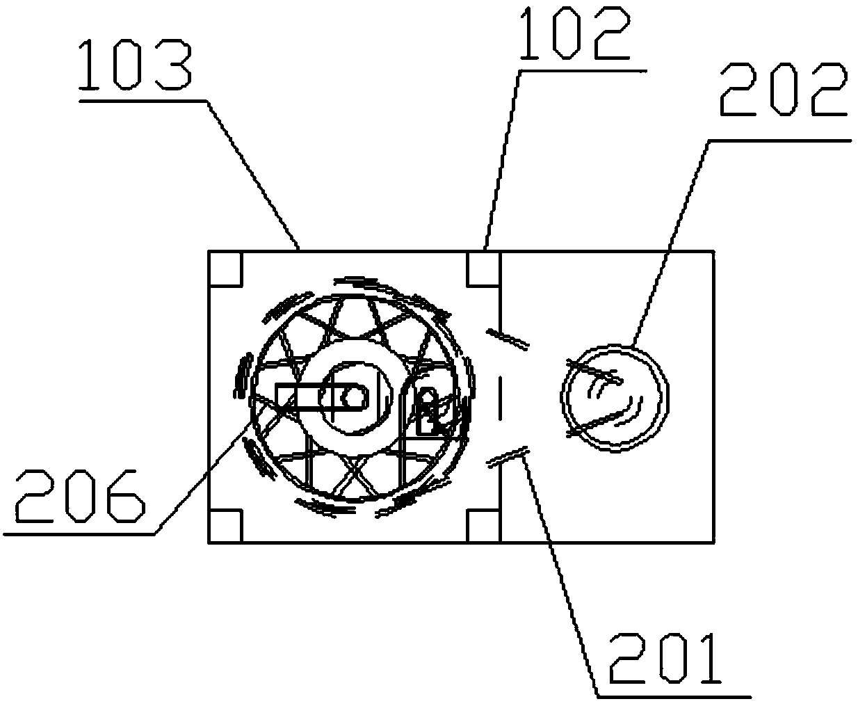
[0032] The heating system 3 includes a steam inlet 301, a heating pipe 302, a steam exhaust port 303, and a baffle 304. The heating pipe 302 is detachably installed on the coaxial installation of the lower support plate 101 and the upper support plate 103. In the hole, the upper part of the heating pipe 302 is provid...
Embodiment 2
[0041] Other features are all described in Embodiment 1. In practical applications, 6 stirring blades 206 are evenly arranged inside the stirring shell 209, and the section of the baffle 304 is fan-shaped at 300 degrees. The rotation elevation angle of the 206 stirring blades is 75 degrees, related to the aspect ratio of the stirring shell 209, the distance between the outer edge of the stirring blade 206 and the outer wall of the heating tube 302 is 8 cm. .
[0042] In summary, the present invention can effectively prevent highly viscous organic sludge from adhering to the stirring system, improve drying efficiency, and reduce steam consumption during the working process.
PUM
 Abstract
Description
Claims
Application Information
 - R&D Engineer
- R&D Manager
- IP Professional
- Industry Leading Data Capabilities
- Powerful AI technology
- Patent DNA Extraction
Browse by: Latest US Patents, China's latest patents, Technical Efficacy Thesaurus, Application Domain, Technology Topic, Popular Technical Reports.
© 2024 PatSnap. All rights reserved.Legal|Privacy policy|Modern Slavery Act Transparency Statement|Sitemap|About US| Contact US: help@patsnap.com