Lifting frame of water cup
A water cup and frame technology, applied in the field of water cup extraction device, can solve the problems of poor stability, easy to leak, etc., and achieve the effect of good stability, not easy to leak, and enhanced stability
- Summary
- Abstract
- Description
- Claims
- Application Information
AI Technical Summary
Problems solved by technology
Method used
Image
Examples
Embodiment 1
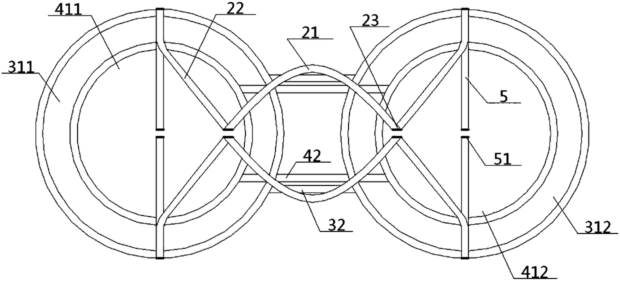
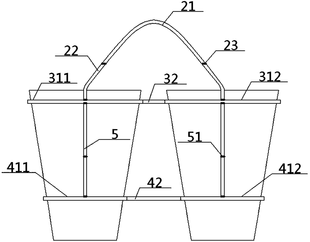
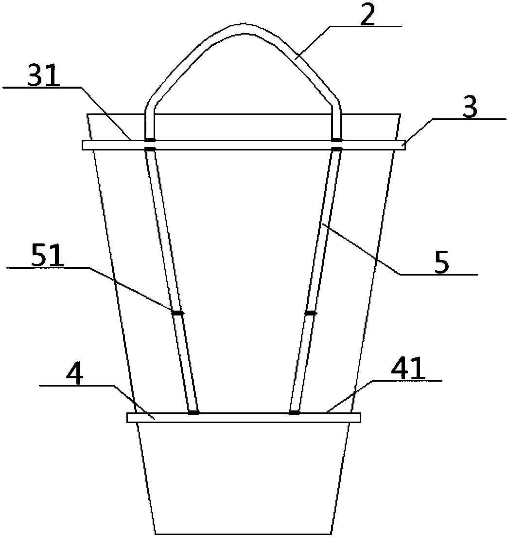
[0029] see Figure 1 to Figure 8 , a carrying frame for a water cup, comprising a cup frame 1 and a handle 2, and the top of the cup frame 1 is connected to the bottom of the handle 2; the cup frame 1 includes an upper ring plate 3 and a lower ring plate 4 With the middle connecting bar 5, the bottom of the handle 2 is hinged with the top surface of the upper ring plate 3, the bottom surface of the upper ring plate 3 is hinged with the top of the middle connecting bar 5, and the lower end of the middle connecting bar 5 is connected with the lower The top surfaces of the ring plates 4 are hinged, and the upper ring plate 3 and the lower ring plate 4 are parallel to each other; the upper ring plate 3 is provided with an upper ring mouth 31, and the lower ring plate 4 is provided with a lower ring mouth 41. The lower ring port 41 is arranged coaxially with the upper ring port 31 directly above it;
[0030] The bottom of the cup holder frame 1 is connected with the heat dissipati...
Embodiment 2
[0032] Basic content is the same as embodiment 1, the difference is:
[0033] The quantity of the upper ring mouth 31 in the described upper ring plate 3 is one, and the quantity of the lower ring mouth 41 in the lower ring plate 4 is also one, and the diameter of the upper ring mouth 31 is greater than the diameter of the lower ring mouth 41; The bar 5 is arranged obliquely, and the distance between the junction of the middle connecting strip 5 and the upper ring plate 3 and the central axis of the upper ring mouth 31 is greater than the distance between the junction of the middle connecting strip 5 and the lower ring plate 4 and the central axis of the lower ring mouth 41.
Embodiment 3
[0035] Basic content is the same as embodiment 1, the difference is:
[0036] The number of upper ring mouths 31 in the upper ring plate 3 is two, which are respectively the left upper ring mouth 311 and the right upper ring mouth 312. The position between the left upper ring mouth 311 and the right upper ring mouth 312 on the upper ring plate 3 is the upper The middle plate 32, the number of the lower ring mouth 41 in the lower ring plate 4 is also two, which are respectively the lower left ring mouth 411 and the lower right ring mouth 412, and the lower ring plate 4 is located at the lower left ring mouth 411 and the lower right ring mouth The position between 412 is the lower middle plate 42, and the lower middle plate 42 is wider than the upper middle plate 32;
PUM
 Abstract
Description
Claims
Application Information
 - R&D
- Intellectual Property
- Life Sciences
- Materials
- Tech Scout
- Unparalleled Data Quality
- Higher Quality Content
- 60% Fewer Hallucinations
Browse by: Latest US Patents, China's latest patents, Technical Efficacy Thesaurus, Application Domain, Technology Topic, Popular Technical Reports.
© 2025 PatSnap. All rights reserved.Legal|Privacy policy|Modern Slavery Act Transparency Statement|Sitemap|About US| Contact US: help@patsnap.com


