A bus bridge based on chained ports and its working method

A working method and bridge technology, applied in the field of aerospace applications, can solve the problems of increasing system complexity, complex design of arbitrators, and large protocol overhead, etc., to achieve the effect of improving port usage efficiency, reducing design risks, and broadening application fields

Active Publication Date: 2020-07-17
XIAN MICROELECTRONICS TECH INST
View PDF13 Cites 0 Cited by
  • Summary
  • Abstract
  • Description
  • Claims
  • Application Information

AI Technical Summary

Problems solved by technology

There are many design modules in this method, and the HDLC protocol is used for transmission, which makes the design more complicated. The size of the FIFO module will restrict the data transmission efficiency. The protocol overhead of the method is large, and the interface performance cannot be effectively utilized.
[0006] Patent application CN 101917318A, title: A high-low speed bus system connection device and high-low speed bus, the patent application provides a high-low speed bus system connection device and high-low speed bus system, the patent application cannot effectively multiplex the bandwidth of the high-speed bus
If multiple bridge circuits are required in the transmission application field of high-speed bus and multiple low-speed buses, the system complexity will be increased
[0007] Chinese patent CN103440219B, name: a universal bus conversion bridge IP core, this patent can solve the bridging of multiple data buses, but the data exchange relies too much on the interrupt control unit and the register control unit, the design of the arbitrator is relatively complicated, the efficiency is not high, and the internal Storage space is not being used effectively

Method used


Image

  • A bus bridge based on chained ports and its working method
  • A bus bridge based on chained ports and its working method
  • A bus bridge based on chained ports and its working method

Examples


Embodiment Construction

[0039] The present invention is described in further detail below:

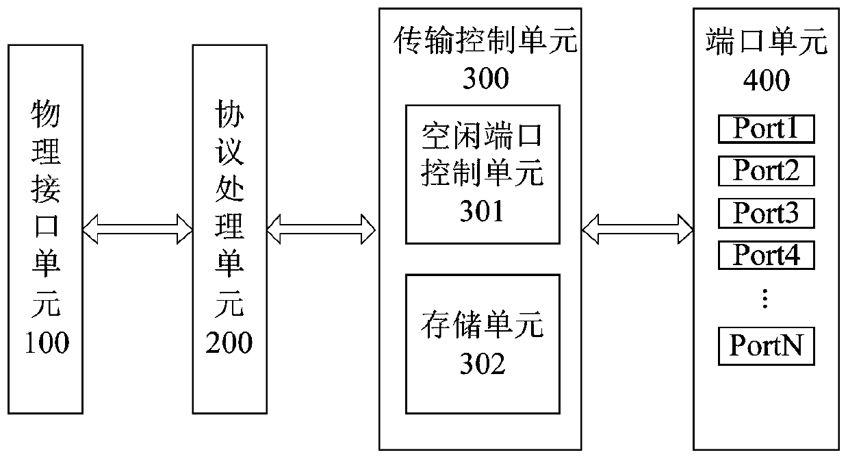
[0040] The bus bridge of the present invention includes a physical interface unit 100, a protocol processing unit 200, a transmission control unit 300 and a port unit 400, and the system structure block diagram is as follows figure 1 shown.

[0041]Among them, the physical interface unit 100 is a physical path for connecting with the external high-speed data bus, the interface meets the physical and electrical characteristics of the external high-speed data bus, sends and receives information according to the electrical characteristics of the external bus, and is bidirectionally connected with the protocol processing unit 200 .

[0042] The protocol processing unit 200 is bidirectionally connected to the physical interface unit 100 and the transmission control unit 300 respectively. The protocol processing unit 200 can analyze the data received by the physical interface unit 100 according to the high-speed b...


PUM


Abstract

The invention discloses a chained port-based bus bridge and its working method, comprising a physical interface unit, a protocol processing unit, a transmission control unit and a port unit; the protocol processing unit is bidirectional with the physical interface unit and the transmission control unit respectively Connection; the transmission control unit includes an idle port control unit and a storage unit, the idle port control unit controls bus data transmission through the idle port linked list, and the storage unit is a dual-port RAM, including a receiving buffer area and a sending buffer area; the port unit includes Several mutually independent ports PORT, each port PORT is connected with the external low-speed data bus, each port PORT contains a sub-protocol processing unit and a physical interface unit inside, and each independent port PORT is bidirectionally connected with the transmission control unit. The invention effectively solves the interconnection problem between a high-speed bus and multiple low-speed buses, and effectively reduces design risks.

Description

technical field [0001] The invention belongs to the field of aerospace applications, in particular to a chain port-based bus bridge and its working method, which is suitable for bridging between high-speed buses and multiple low-speed buses. Background technique [0002] With the continuous expansion of aerospace applications, the increasingly complex and diverse space exploration missions put forward higher requirements for spacecraft data networks. In the field of space applications, limited by the requirements of the design structure and application scenarios, the data network not only has a complex topology, but also uses different bus protocols. In order to meet the data interaction in complex networks, a large number of bus bridge modules are usually required. According to the ESA spacecraft development roadmap, the backbone data bus of the future spacecraft will use the SpaceFibre bus for Gbps-level high-reliability and high-speed data transmission requirements, and ...

Claims


Application Information

Patent Timeline
Patent Type & Authority Patents(China)
IPC IPC(8): H04L12/40H04L12/46H04L12/879H04L12/883H04L49/901H04L49/9015
CPCH04L12/40032H04L12/4625H04L49/901H04L49/9015
Inventor 任永杰陈卫国王剑峰
Owner XIAN MICROELECTRONICS TECH INST
Why Eureka
Try Eureka