
Shift register unit, driving method, gate driving circuit and display device

A shift register and gate driving technology, applied in the fields of driving methods, shift register units, gate driving circuits and display devices, can solve problems such as unfavorable narrow borders, low charging rate, inability to effectively reduce voltage values, etc.

Active Publication Date: 2018-10-12
BOE TECH GRP CO LTD +1
View PDF8 Cites 5 Cited by
  • Summary
  • Abstract
  • Description
  • Claims
  • Application Information

AI Technical Summary

Problems solved by technology

[0003] The main purpose of the present invention is to provide a shift register unit, a driving method, a gate driving circuit and a display device, so as to solve the problem that the voltage value of the high voltage VGH that needs to be provided cannot be effectively reduced in the prior art, resulting in a low charging rate and not Facilitate the realization of narrow borders

Method used


Image

  • Shift register unit, driving method, gate driving circuit and display device
  • Shift register unit, driving method, gate driving circuit and display device
  • Shift register unit, driving method, gate driving circuit and display device

Examples


Embodiment approach

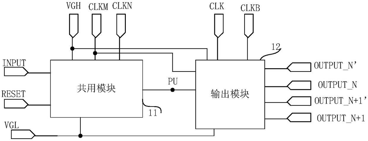
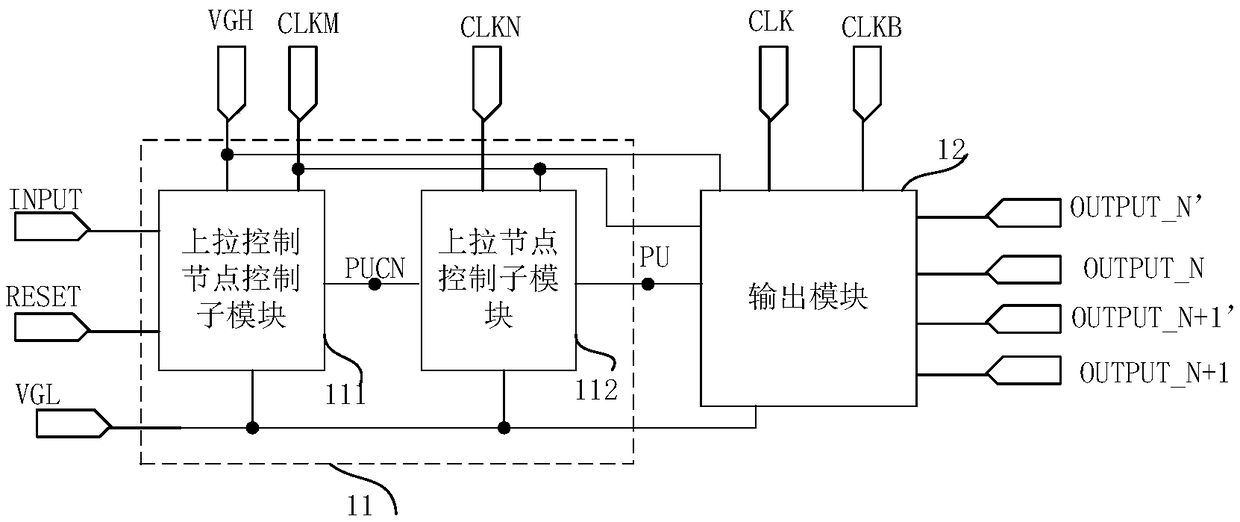
[0116] According to a specific implementation manner, the noise reduction control terminal includes a third clock signal input terminal and a fourth clock signal input terminal, and the output control terminal includes a first clock signal input terminal;

[0117] M is equal to 2, and the shift register unit includes a first gate drive signal output terminal, a second gate drive signal output terminal, a third gate drive signal output terminal and a fourth gate drive signal output terminal;

[0118] The output modules include:

[0119]a first output transistor, the gate of which is connected to the pull-up node, the first pole is connected to the first gate drive signal output terminal, and the second pole is connected to the fourth clock signal input terminal;

[0120] For a second output transistor, the gate is connected to the pull-up node, the first pole is connected to the third clock signal input terminal, and the second pole is connected to the second gate drive signal ...


PUM


Abstract

The invention provides a shift register unit, a driving method, a gate driving circuit and a display device. The shift register unit comprises a sharing module and an output module; the sharing modulecontrols the potential of a pull-up node under the control of a input end, a reset end and a first clock signal input end; the output module is used for controlling grid driving signals output by 2Mgrid driving signal output ends under the control of the pull-up node, a noise-reducing control end and an output control end; wherein M is an integer greater than 2. The charging rate of shift register unit is high, and the narrow frame can be conveniently realized.

Description

technical field [0001] The invention relates to the technical field of display driving, in particular to a shift register unit, a driving method, a gate driving circuit and a display device. Background technique [0002] In the existing display device, the driving transistor in the pixel circuit is an ordinary thin film transistor with only one gate, which cannot effectively reduce the voltage value of the high voltage VGH that needs to be provided, resulting in a low charging rate. In addition, the number of shift register units included in the existing gate drive circuit needs to be the same as the number of rows of pixel circuits set on the display panel, and it is not possible to use one-stage shift register units for at least two rows of pixel circuits to be connected to the corresponding gates, respectively. Pole drive signals, so a large number of transistors need to be used, which is not conducive to the realization of narrow borders. Contents of the invention [...

Claims


Application Information

Patent Timeline
IPC IPC(8): G09G3/20G11C19/28
CPCG09G3/20G09G2310/0267G09G2310/0286G11C19/28G09G3/3677G09G2300/0426G09G2310/08G09G2320/0209G11C19/287
Inventor 许卓金相洙白雅杰但艺吴海龙
Owner BOE TECH GRP CO LTD
Learn More