
Humidifying device

A technology of humidification device and installation structure, which is applied in the direction of air humidification system, heating method, pipeline layout, etc., which can solve the problems of high replacement cost of air conditioner and poor humidification effect, and achieve the effect of improving humidification effect, increasing service life and reducing noise

Active Publication Date: 2018-10-12
QINGDAO HAIER AIR CONDITIONER GENERAL CORP LTD +2
View PDF6 Cites 2 Cited by
  • Summary
  • Abstract
  • Description
  • Claims
  • Application Information

AI Technical Summary

Problems solved by technology

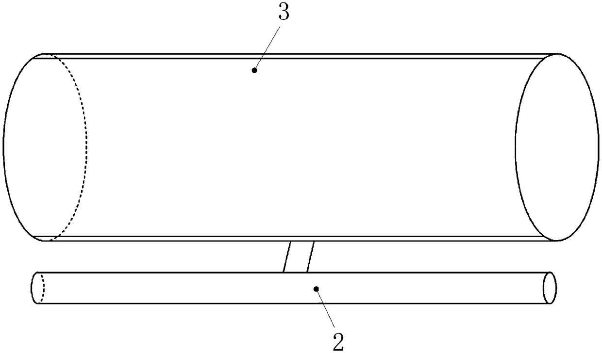
[0005] In order to solve the above-mentioned problems in the prior art, that is, in order to solve the problems of poor humidification effect of existing humidifiers and high replacement cost of air conditioners with humidification function, the present invention provides a humidification device, which includes a humidification module and The air supply module, the humidification module includes a shell, a water collection system and a drainage system communicated with each other, and a semiconductor water collection assembly is arranged in the casing, and the semiconductor water collection assembly includes a cooling end and a heat dissipation end; the water collection system It includes a water-collecting air inlet, a water-collecting air outlet, a water-collecting fan and the cooling end arranged between the water-collecting air inlet and the water-collecting air outlet, and the water-collecting system is arranged in the Driven by the water-collecting fan, the outdoor air is introduced into the shell through the water-collecting air inlet and passes through the cooling end, and then discharged out of the shell through the water-collecting air outlet; the drainage system includes a drainage air intake mouth, drainage air outlet, and the drainage fan and the heat dissipation end arranged between the drainage air inlet and the drainage air outlet, the drainage system is set to pass the outdoor air through the The drainage air inlet is introduced into the housing and passes through the heat dissipation end, and then introduced into the room through the drainage air outlet; the air supply module includes a tubular shell, and the tubular shell is provided with a support communicating with it tube, the air supply module is installed to the position to be installed through the support tube, and the support tube is provided with an air inlet hole, and the air inlet hole is connected with the drainage outlet through a connecting pipe, and the tubular The casing is provided with air outlet holes, and the air outlet holes are arranged in the tubular casing along the length direction of the tubular casing

Method used


Image

  • Humidifying device
  • Humidifying device
  • Humidifying device

Examples


Embodiment Construction

[0028] The preferred embodiments of the present invention will be described below with reference to the drawings. Those skilled in the art should understand that these embodiments are only used to explain the technical principles of the present invention and are not intended to limit the protection scope of the present invention. For example, although two sets of air supply mechanisms are provided in the air supply module in the drawings, this arrangement form is not static, and those skilled in the art can make adjustments as needed to adapt to specific applications. For example, one or more sets of air blowing mechanisms may also be provided in the air blowing module, as long as the air blowing mechanism can play a role of pressurizing and diverting the air flow entering the air blowing module.

[0029] It should be noted that in the description of the present invention, the terms "center", "upper", "lower", "left", "right", "vertical", "horizontal", "inner", "outer", etc. The...


PUM


Abstract

The invention relates to the technical field of air conditioning, in particular to a humidifying device, and aims to solve the problems that a conventional humidifier is poor in humidifying effect andan air conditioner with a humidifying function is high in replacement cost. To achieve the purpose, the humidifying device comprises a humidification module and an air supply module, wherein the humidification module comprises a housing, as well as a water collection system and a drainage system which communicate with each other; a semi-conductor water collection component is arranged in the housing; the water collection system comprises a water collection air inlet, a water collection air outlet, a water collection fan and a refrigerating end of the semiconductor water collection component;the drainage system comprises a drainage air inlet, a drainage air outlet, a drainage fan and a heat dissipation end of the semiconductor water collection component; the air supply module comprises atubular housing and a support tube; an air inlet hole is formed in the support tube; an air outlet hole is formed in the tubular housing; and the air inlet hole and the drainage air outlet communicatewith each other through a connecting pipe. By adoption of the mode, the humidifying device is obviously improved in humidifying effect and lowered in replacement cost.

Description

Technical field [0001] The invention relates to the technical field of air conditioning, in particular to a humidification device. Background technique [0002] Ambient temperature is the index that can directly affect people's living environment. Compared with environmental temperature, environmental humidity is also closely related to human health and daily life. Medical research shows that when the ambient temperature is 20-25°C and the relative humidity reaches 45-65%, the human body and mind are in the best state, and the ideal results can be achieved regardless of work or rest. However, with the improvement of people's living standards, especially the widespread use of air conditioners, the problems caused by the drop in indoor humidity have become more prominent. Take the air conditioner heating as an example. When the air conditioner operates in the heating mode to make the indoor temperature reach a better temperature range, the indoor humidity will drop to a certain v...

Claims


Application Information

Patent Timeline
IPC IPC(8): F24F6/12F24F6/10F24F7/06F24F13/28F24F13/02F24F13/22F24F13/24
CPCF24F6/10F24F6/12F24F7/065F24F13/02F24F13/222F24F13/24F24F13/28F24F2013/225F24F2013/247
Inventor 刘光朋马令庆胡兰岐
Owner QINGDAO HAIER AIR CONDITIONER GENERAL CORP LTD
Learn More