High-abrasion-resistance-strength spring supporting and hanging frame
A kind of support hanger, high wear resistance technology, applied in the direction of pipeline support, supporting machine, furnace type, etc., can solve the problems of short practical life, poor strength and other performance of spring hanger, easy to cause danger, etc., to achieve long service life, Good performance, good effect
- Summary
- Abstract
- Description
- Claims
- Application Information
AI Technical Summary
Problems solved by technology
Method used
Image
Examples
Embodiment 1
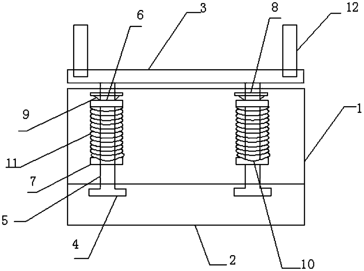
[0037] A high wear-resistant strength spring hanger provided in this embodiment has a structure such as figure 1 As shown, it includes a base 2, a cylinder 1 and a pillar 5, the pillar 5 runs through the cylinder 1, the base 2 is arranged at the bottom of the cylinder 1, T-shaped grooves are provided on both sides of the base 2, and the bottom of the pillar 5 is provided with a T The T-shaped connecting block 4 that is compatible with the structure of the T-shaped groove, the T-shaped connecting block 4 is installed in the T-shaped groove of the base, and is fixed on the base by screws, and the pillar 5 is provided with an upper limit block 6 and a lower limit Position block 7, and at upper limit block 6 and lower limit block 7, spring 11 is sleeved on the outside of pillar 5, and the upper end of spring 11 is against upper limit block 6, and the outer diameter of upper limit block 6 and spring 11 inner diameter Same, the lower end and the lower limit block 7 are provided with...
Embodiment 2
[0057] A high wear-resistant strength spring hanger provided in this embodiment has a structure such as figure 1 As shown, it includes a base 2, a cylinder 1 and a pillar 5, the pillar 5 runs through the cylinder 1, the base 2 is arranged at the bottom of the cylinder 1, T-shaped grooves are provided on both sides of the base 2, and the bottom of the pillar 5 is provided with a T The T-shaped connecting block 4 that matches the structure of the T-shaped groove, the T-shaped connecting block 4 is installed in the T-shaped groove of the base, and is fixed on the base by screws, and the upper limit block 6 and the lower limit block are arranged on the pillar 5 Position block 7, and at upper limit block 6 and lower limit block 7, spring 11 is sleeved on the outside of pillar 5, and the upper end of spring 11 abuts against upper limit block 6, and the outer diameter of upper limit block 6 and spring 11 inner diameter Same, the lower end and the lower limit block 7 are provided with...
PUM
| Property | Measurement | Unit |
|---|---|---|
| Diameter | aaaaa | aaaaa |
Abstract
Description
Claims
Application Information
 - R&D
- Intellectual Property
- Life Sciences
- Materials
- Tech Scout
- Unparalleled Data Quality
- Higher Quality Content
- 60% Fewer Hallucinations
Browse by: Latest US Patents, China's latest patents, Technical Efficacy Thesaurus, Application Domain, Technology Topic, Popular Technical Reports.
© 2025 PatSnap. All rights reserved.Legal|Privacy policy|Modern Slavery Act Transparency Statement|Sitemap|About US| Contact US: help@patsnap.com

