A multi-stage combined recovery device for vehicle engine exhaust energy

A recovery device and engine technology, applied to exhaust devices, engine components, combustion engines, etc., can solve the problems of single recovery, no comprehensive consideration of exhaust energy distribution, no comprehensive recovery of on-board engines, etc.

Active Publication Date: 2020-06-19
HUNAN UNIV
View PDF12 Cites 1 Cited by
  • Summary
  • Abstract
  • Description
  • Claims
  • Application Information

AI Technical Summary

Problems solved by technology

CN201510064451 Chinese invention patent An engine energy recovery system, which makes full use of the heat of the engine, which is the maximum energy of the engine, by setting an auxiliary supercharging device, and reuses it in the power recovery and utilization of the engine, but this method is also a single recovery extra kinetic energy
To sum up, these existing technologies only recover part of the exhaust energy of the vehicle-mounted engine, and do not comprehensively recover the energy of the vehicle-mounted engine, nor do they fully consider the distribution of exhaust energy, and do not recover exhaust energy to the maximum extent. Qi energy

Method used


Image

  • A multi-stage combined recovery device for vehicle engine exhaust energy
  • A multi-stage combined recovery device for vehicle engine exhaust energy
  • A multi-stage combined recovery device for vehicle engine exhaust energy

Examples


Embodiment Construction

[0048] The specific embodiments of the present invention will be further described in detail below with reference to the accompanying drawings and embodiments. The following examples are only used to illustrate the present invention, but not to limit the scope of the present invention.

[0049] Orientation terms such as upper, lower, left, right, front and rear in this application document are established based on the positional relationship shown in the accompanying drawings. If the drawings are different, the corresponding positional relationship may also change accordingly, so this should not be construed as a limitation on the protection scope.

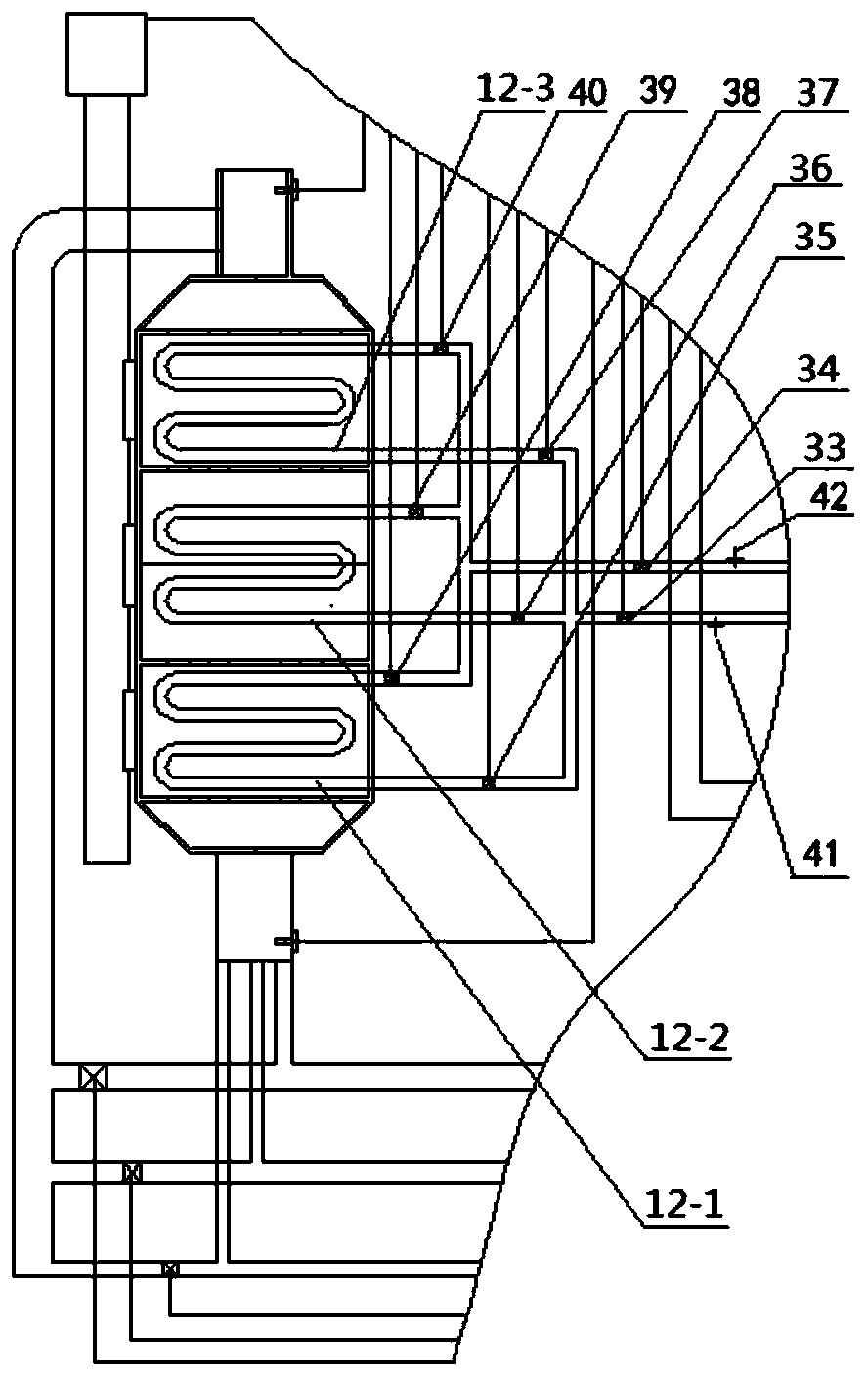
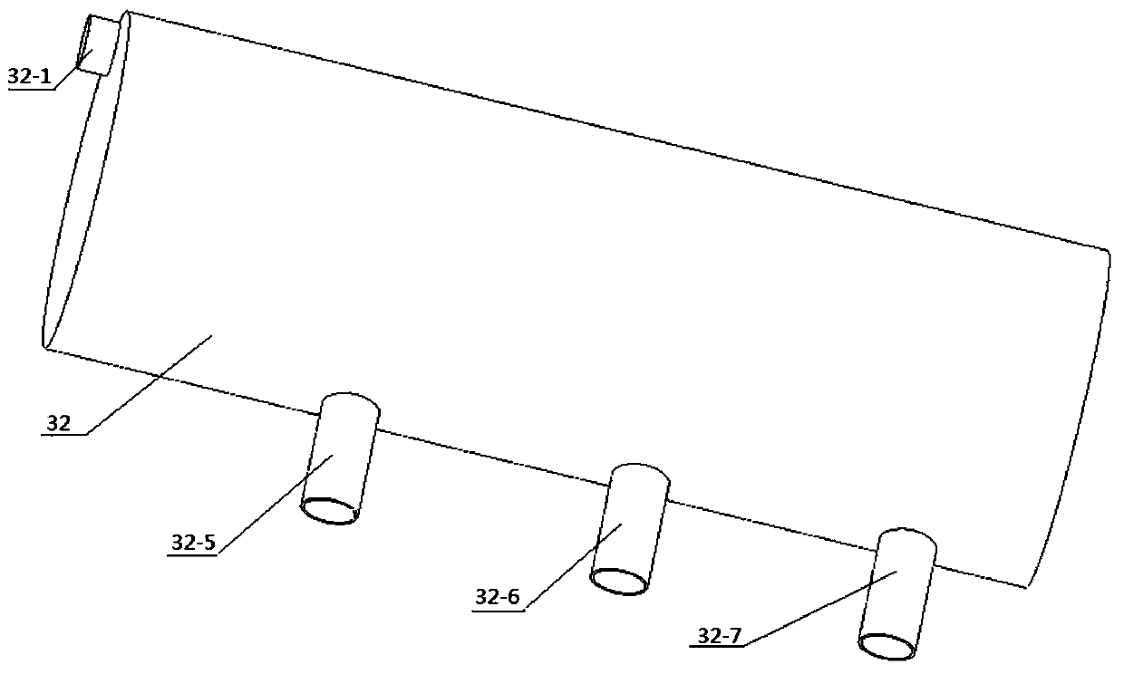
[0050] This embodiment describes a multi-stage combined recovery device for vehicle-mounted engine exhaust energy, which performs multi-level combined recovery of vehicle-mounted engine exhaust energy. The recovery device such as figure 1 and figure 2As shown, including electronic control unit 1, speed sensor 2, vehicle engine...


PUM


Abstract

The invention relates to a multi-stage united recycling device for exhaust energy of a vehicle-mounted engine. The multi-stage united recycling device comprises an electronic control unit, a rotatingspeed sensor, the vehicle-mounted engine, an intake manifold, an electronic throttle valve, a waste heat energy recycling device, an exhaust inlet, a high-speed turbine, a mid-speed turbine, a low-speed turbine, an intake compressor, an exhaust manifold, a high-speed exhaust electromagnetic valve, a mid-speed exhaust electromagnetic valve, a low-speed exhaust electromagnetic valve and a waste kinetic energy and waste pressure energy conversion device, wherein the on-off of the high-speed exhaust electromagnetic valve, the mid-speed exhaust electromagnetic valve and the low-speed exhaust electromagnetic valve is controlled by the electronic control unit, so that the intake compressor is combined with the corresponding started high-speed turbine, mid-speed turbine or low-speed turbine to form a turbo charger used for recycling waste kinetic energy and waste pressure energy in exhaust, the exhaust can be discharged into the waste heat energy recycling device through the high-speed turbine, the mid-speed turbine or the low-speed turbine, and then waste heat energy can be recycled. By adoption of the multi-stage united recycling device provided by the invention, the multi-stage united cascade recycling of energy in the exhaust of the vehicle-mounted engine can be achieved.

Description

technical field [0001] The invention relates to a vehicle-mounted engine exhaust energy recovery device, in particular to a vehicle-mounted engine exhaust energy multi-stage combined recovery device. Background technique [0002] With the sustained and steady development of the economy, the urban traffic vehicles and cars have grown rapidly, and the pollution of various motor vehicle exhaust emissions has become increasingly serious. The air pollution in many large cities in China has shifted from coal-fired pollution to coal-fired and machine-based pollution Motor vehicles are mixed with pollution, and motor vehicle exhaust pollutants and carcinogens have caused serious harm to the environment and people's health. Although motor vehicle exhaust pollution has aroused widespread concern in the society, and the state has formulated stricter regulations, various measures need to be further strengthened and implemented, and the governance is far from enough. At the same time, t...

Claims


Application Information

Patent Timeline
Patent Type & Authority Patents(China)
IPC IPC(8): F02D29/02F01N5/02F01N5/04F02B37/00F02N19/10
CPCF01N5/02F01N5/025F01N5/04F02B37/001F02D29/02F02N19/10Y02T10/12
Inventor 段雄波刘敬平袁志鹏刘琦李洋洋皱鹏
Owner HUNAN UNIV
Why Eureka
Try Eureka