Chemical fibre cloth cutter

A cut-off and cloth technology, which is applied in the cutting of textile materials, textiles and papermaking, etc., can solve the problems of inconvenience of rare earth heaters, heat dissipation of heat dissipation heaters in connectors, etc.

Inactive Publication Date: 2018-10-12
长兴明远布艺科技有限公司
View PDF1 Cites 0 Cited by
  • Summary
  • Abstract
  • Description
  • Claims
  • Application Information

AI Technical Summary

Problems solved by technology

[0004] The purpose of the present invention is to provide a chemical fiber cloth cutter to solve the problem that the existing rare earth heaters are not convenient for multi-applicability, provide precise temperature control effects and the heat loss of the heaters caused by the heat dissipation of the connecting parts

Method used


Image

  • Chemical fibre cloth cutter
  • Chemical fibre cloth cutter
  • Chemical fibre cloth cutter

Examples


Embodiment Construction

[0019] The following will clearly and completely describe the technical solutions in the embodiments of the present invention with reference to the accompanying drawings in the embodiments of the present invention. Obviously, the described embodiments are only some, not all, embodiments of the present invention. Based on the embodiments of the present invention, all other embodiments obtained by persons of ordinary skill in the art without making creative efforts belong to the protection scope of the present invention.

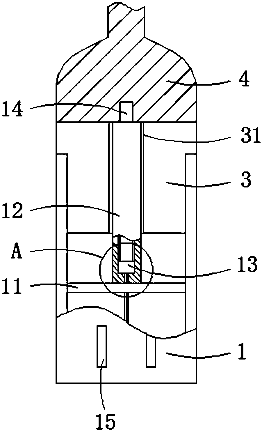
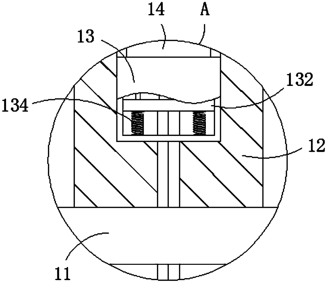
[0020] see Figure 1-Figure 4 As shown, the present invention provides the following technical solution: the chemical fiber fabric cutter includes a connecting piece 1, one end of the connecting piece 1 is fixedly connected with a handle 2 through a bolt, and the end of the connecting piece 1 away from the handle 2 is connected with a The cutter head 4, the inside of the connector 1 is welded with a mounting plate 11, and one side of the mounting plate 11 is w...


PUM


Abstract

The invention discloses a chemical fiber cloth cutter, which comprises a connecting element, one end of the connecting element is fixedly connected with a handle through bolts, one end of the connecting element, far away from the handle, is connected with a cutter head through an outer heat insulation sleeve, a mounting plate is welded inside the connecting element, one side of the mounting plateis welded with an inner heat insulation sleeve, the inner part of the inner heat insulation sleeve is internally provided with a connecting switch and a heating element, the heating element is locatedat one side of the connecting switch, and one end of the heating element, away from the connecting switch, is engaged with the inside of the cutter head, and a plurality of cooling holes are arrangedat the position of the outer wall of the connecting element located at the mounting plate, away from the side of the inner insulating sleeve. According to the invention, the connecting switch and theheating element are arranged, during the initial heating process, the connecting switch is in an ON state, the conductive column inside the connecting switch is in full contact with the conductive contact on the heating element, and the heating wires inside the heating element is in a heating state so that the heating element is in a rapid heating state.

Description

technical field [0001] The invention belongs to the technical field of chemical fiber cloth, in particular to a chemical fiber cloth cutter. Background technique [0002] Chemical fiber fabrics mainly refer to pure, blended or interwoven fabrics processed from chemical fibers, that is to say, fabrics woven from purified fibers, and chemical fiber fabrics need to be cut according to specific needs during the production process. In the process, the fabric is first cut with a cutting knife, and then the edge of the cut fabric is ironed with an electric iron to prevent the fabric fibers from falling off. [0003] In the Chinese patent with the patent number CN201924217U, a chemical fiber cloth cutter is proposed. By setting the cutter head and the electric heater, the cutting and anti-off processes are combined, which simplifies the process and reduces the labor intensity of the operator. Effective The working efficiency is improved, but, in the above-mentioned equipment, by us...

Claims


Application Information

Patent Timeline
Patent Type & Authority Applications(China)
IPC IPC(8): D06H7/22
CPCD06H7/221
Inventor 王利勇沈月红王伟红张如女沈会义
Owner 长兴明远布艺科技有限公司
Why Eureka
Try Eureka