
Rotary feeding device for new energy material processing

A new energy material and rotary feeding technology, which is applied in the field of rotary feeding device for new energy material processing, can solve the problems that materials cannot be transferred to another platform, cannot realize rotary feeding, and reduce labor intensity, etc., so as to ensure the use of Effect and use benefit, firm clamping, and flexible use

Inactive Publication Date: 2018-10-12
HUAIBEI ZHIHUAI TECH CO LTD
View PDF7 Cites 0 Cited by
  • Summary
  • Abstract
  • Description
  • Claims
  • Application Information

AI Technical Summary

Problems solved by technology

[0002] New energy materials need to be fed during the processing process. The structure of the traditional feeding device is relatively fixed, and the conveyor belt is generally used for direct feeding. For example, the application number is CN201720065189.1, which is an automatic cutting and feeding device for mud blanks in ceramic production lines. Push the slider to move left and right through the first hydraulic cylinder, which is convenient for adjusting the cutting length and quantitative cutting, and push the cutting knife assembly to move up and down through the second hydraulic cylinder, which is convenient for cutting. Through the design of the third hydraulic cylinder and the fourth hydraulic cylinder, and then With the use of the cylinder, the fixture body is close to the cut mud body, and the cut mud body is clamped and placed on the mold body, which is convenient for the next step of processing, instead of manual operation, with high work efficiency and reduced labor intensity. However, the above-mentioned scheme still has certain defects. It cannot realize rotary feeding, and cannot transfer materials from one platform to another, which has certain limitations.

Method used


Image

  • Rotary feeding device for new energy material processing
  • Rotary feeding device for new energy material processing
  • Rotary feeding device for new energy material processing

Examples


Embodiment Construction

[0018] The following will clearly and completely describe the technical solutions in the embodiments of the present invention with reference to the accompanying drawings in the embodiments of the present invention. Obviously, the described embodiments are only some, not all, embodiments of the present invention. Based on the embodiments of the present invention, all other embodiments obtained by persons of ordinary skill in the art without making creative efforts belong to the protection scope of the present invention.

[0019] In the present invention, it should be noted that the terms "center", "upper", "lower", "left", "right", "vertical", "horizontal", "inner", "outer" etc. indicate The orientation or positional relationship is based on the orientation or positional relationship shown in the drawings, and is only for the convenience of describing the present invention and simplifying the description, rather than indicating or implying that the referred device or element mus...


PUM


Abstract

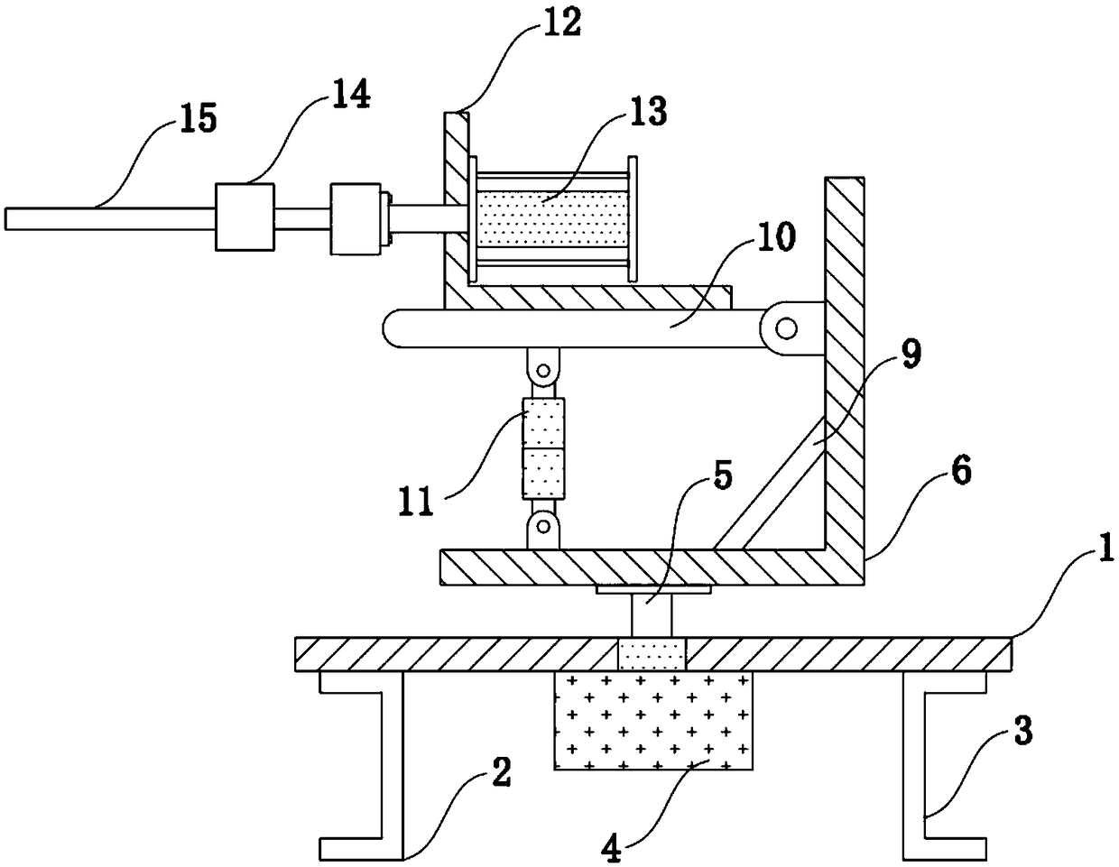
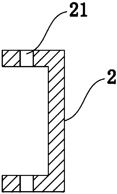
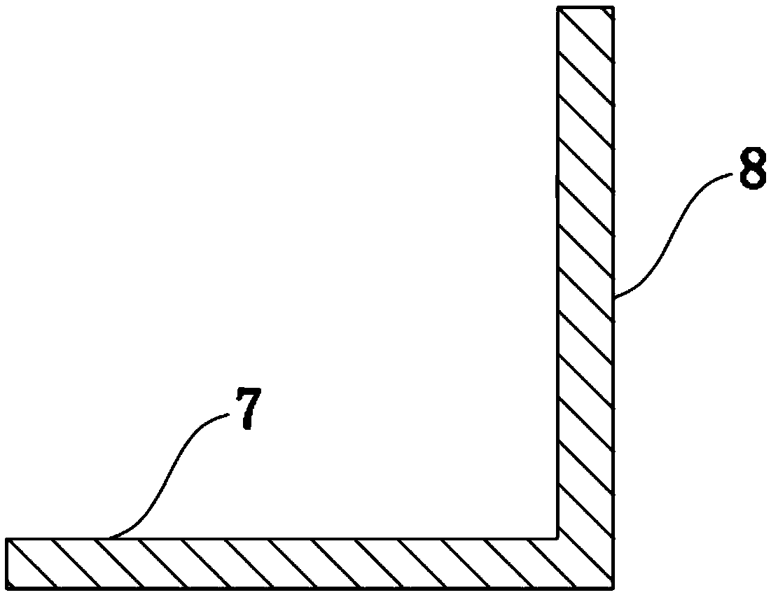
The invention discloses a rotary feeding device for new energy material processing. The rotary feeding device comprises a base, a first fixing frame and a second fixing frame are symmetrically arranged on the left side and the right side of the bottom of the base, a motor is installed in the middle of the bottom of the base, the left side of the top of a first machine frame is movably connected with a hydraulic cylinder body through a pin, the output end of the hydraulic cylinder body is movably connected with a supporting frame through a pin, and the left end of the supporting frame is movably connected to a second machine frame through a pin; a mounting frame is installed on the supporting frame, and is L-shaped, an air cylinder body is fixedly installed on the mounting frame, the outputend of the air cylinder body is fixedly connected with a connecting block, and a clamping mechanism is fixed on the connecting block. A traditional feeding device structure is changed, a first clamping plate and a second clamping plate can achieve the actions of clamping and loosening so that materials can be clamped and loosened conveniently, rotary feeding is realized, and the materials can betransferred from one platform to another platform.

Description

technical field [0001] The invention relates to the technical field of new energy materials, in particular to a rotary feeding device for processing new energy materials. Background technique [0002] New energy materials need to be fed during the processing process. The structure of the traditional feeding device is relatively fixed, and the conveyor belt is generally used for direct feeding. For example, the application number is CN201720065189.1, which is an automatic cutting and feeding device for mud blanks in ceramic production lines. Push the slider to move left and right through the first hydraulic cylinder, which is convenient for adjusting the cutting length and quantitative cutting, and push the cutting knife assembly to move up and down through the second hydraulic cylinder, which is convenient for cutting. Through the design of the third hydraulic cylinder and the fourth hydraulic cylinder, and then With the use of the cylinder, the fixture body is close to the ...

Claims


Application Information

Patent Timeline
Patent Type & Authority Applications(China)
IPC IPC(8): B65G47/90
CPCB65G47/904
Inventor 朱颖王玉婷
Owner HUAIBEI ZHIHUAI TECH CO LTD
Learn More