Z-axis chip removal structure of horizontal machining center

A Z-axis, horizontal technology, applied in the field of Z-axis chip removal structure, can solve the problems of time-consuming and laborious, low efficiency, incomplete cleaning of waste and other problems, and achieve the effect of preventing damage

Inactive Publication Date: 2018-10-12
NANTONG GUOSHENG INTELLIGENCE TECH GRP CO LTD
View PDF8 Cites 0 Cited by
  • Summary
  • Abstract
  • Description
  • Claims
  • Application Information

AI Technical Summary

Problems solved by technology

[0002] When the machining center processes parts, chips will be generated, and a large amount of chips will accumulate in the chip removal base. After a period of processing and production, the chip removal base needs to be cleaned regularly. For large-scale machining centers, the waste around the chip removal base Chip workers generally use a brush to remove chips, but the workers cannot remove the waste chips at the corners of the chip removal base with the brush, which creates a dead angle, and when the distance is long, they need to stand in the chip removal base to remove them, which is inefficient. Time-consuming and labor-intensive, and incomplete cleaning of waste debris will lead to oil-water separation in the later stage

Method used


Image

  • Z-axis chip removal structure of horizontal machining center
  • Z-axis chip removal structure of horizontal machining center
  • Z-axis chip removal structure of horizontal machining center

Examples


Embodiment

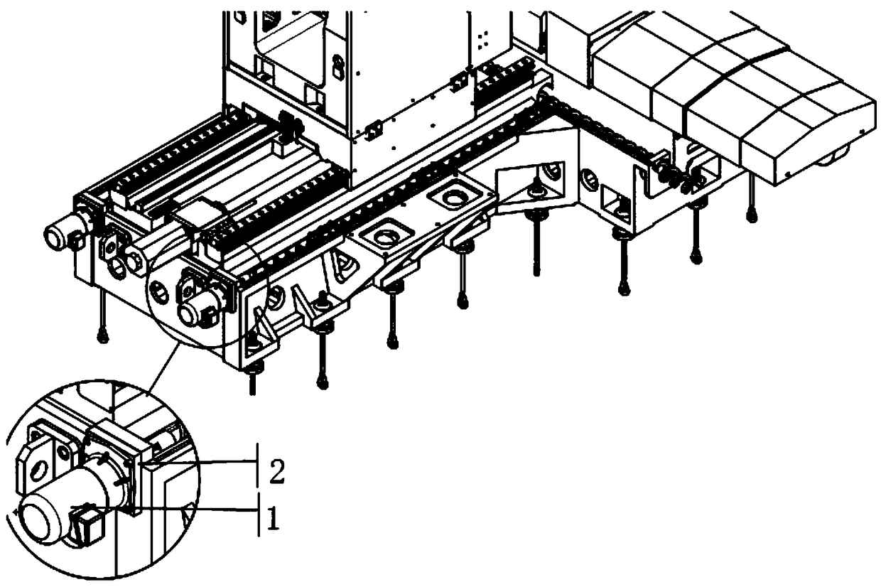
[0014] A Z-axis chip removal structure of a precision horizontal machining center includes a driving part, a chip conveyor (including Jiaolong and a universal joint), and parts of a pressure plate of the chip conveyor.

[0015] Driving part: The driving part is composed of a motor 1 and a motor connecting plate 2. The motor 1 is installed on the motor connecting plate 2, and the motor connecting plate 2 has an open ring groove, and is equipped with an O-ring, which is installed on the outer surface of the bed to avoid damage during processing. Cutting fluid seeps out of the machine tool. The specific installation method is as figure 1 shown.

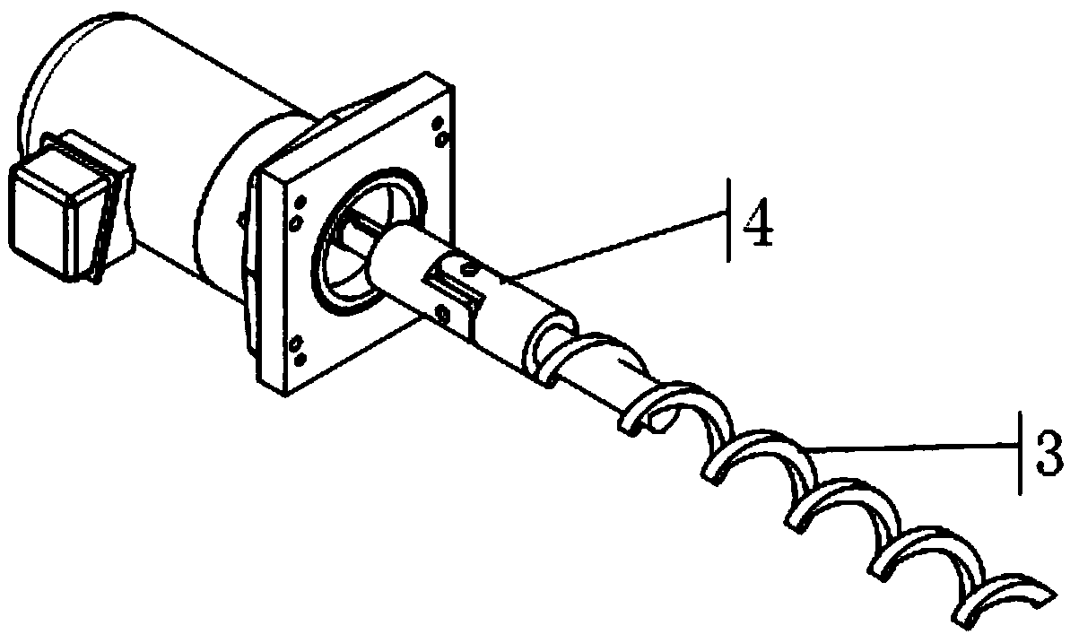
[0016] Spiral chip conveyor (including Jiaolong and universal joint): The spiral chip conveyor is welded by Jiaolong 3 and universal joint in 4 axes. The groove of the chip conveyor is not necessarily flat when the bed is cast, so the universal joint Under the control of 4, it can cooperate with the chip conveyor groove to discharge th...


PUM


Abstract

The invention discloses a Z-axis chip removal structure of a horizontal machining center. The Z-axis chip removal structure comprises a driving part, a spiral chip removal device (containing a packingauger and an universal joint) and a spiral chip removal device pressing plate part. According to the Z-axis chip removal structure of the horizontal machining center, the horizontal machining centerZ-direction accumulated chips are driven to a X-direction chip removal groove through the auger from driving to the Z-direction, and a machine tool large cover is discharged through the X-direction chip removal structure; and the mechanism can solve the problem of chip accumulation in the inclined chip removal process of a machine body, accumulated chips are prevented from accumulating and damaging a Y-direction wire rail sliding block, meanwhile, accumulated chips are prevented from leaking out of the machine body, and the working environment can not be polluted.

Description

technical field [0001] The invention specifically relates to a Z-axis chip removal structure of a horizontal machining center. Background technique [0002] When the machining center processes parts, chips will be generated, and a large amount of chips will accumulate in the chip removal base. After a period of processing and production, the chip removal base needs to be cleaned regularly. For large-scale machining centers, the waste around the chip removal base Chip workers generally use brushes to remove chips, but workers cannot remove chips from the corners of the chip removal base with brushes, resulting in dead corners, and when the distance is far away, they need to stand in the chip removal base to remove them, which is inefficient. Time-consuming and labor-intensive, and incomplete cleaning of waste debris will lead to oil-water separation in the later stage. Contents of the invention [0003] Purpose of the invention: In order to solve the deficiencies of the pr...

Claims


Application Information

Patent Timeline
Patent Type & Authority Applications(China)
IPC IPC(8): B23Q1/25B23Q11/00
CPCB23Q1/25B23Q11/0042
Inventor 徐新朋潘卫国任东石征飞缪申
Owner NANTONG GUOSHENG INTELLIGENCE TECH GRP CO LTD
Why Eureka
Try Eureka